Continue to Site

Welcome to our site!

Electro Tech is an online community (with over 170,000 members) who enjoy talking about and building electronic circuits, projects and gadgets. To participate you need to register. Registration is free. Click here to register now.

  • Welcome to our site! Electro Tech is an online community (with over 170,000 members) who enjoy talking about and building electronic circuits, projects and gadgets. To participate you need to register. Registration is free. Click here to register now.

Soldering Two PCBs Together - Looking for Ideas

Status
Not open for further replies.

JonSea

Well-Known Member
Most Helpful Member
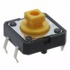
I have a circuit board with 12mm tactile switches and caps that extend through a 3mm acrylic panel. I want to add a piezo beeper that will be flush against the back of the panel, but the beepers are slightly too thick to match the switch height. If I make a sub-board to mount the beepers through a hole in the main board, the elevation is almost perfect, and I can mount the beeper just a bit off the sub board to fit exactly right.

I'm trying to figure out the best way to solder the sub board to the back of the main board. I want minimal thickness between the 2 boards. I guess castellated holes would be the usual approach, but this increases board costs significantly. The main board is mostly surface mount, so one way to do it would be some matching pads on the two boards with solderpaste. Or maybe some large-ish plated through holes soldered with paste or by hand. I could also just insert a screw through each hole and depend on the annular rings making good-enough contact.

Anybody done anything like this? Suggestions?
 
A picture may make this more clear....
elevations.jpg
 
piezo beeper
What is the part number? Data sheet?
Are the other parts through hole or surface mount?

I moved the PCB back one step to make the beeper work. Then added a PCB spacer to keep the switches at the right place. The switch spacers are a simple blank PCB with holes for the switch wires to pass through. (assuming the legs on the switches are long)
1537745420350.png
 
Last edited:
The beepers are actually magnetic rather than piezo - they work well in my application and have a not-unpleasant tone. There are a couple pics from an ebay listing below.

The ideal spacing between panel and pcb is 8mm + a nylon washer to get the switch elevation right - yes, that's probably 9mm, but standoffs typically don't come in 9mm length. The beepers are 9.6mm tall, which works ok with an 8mm standoff and 2 washers, but then the switches are very nearly flush with the panel. That might be ok or even desirable for some applications, but it's less than ideal for mine.

I had thought about spacers behind the switches, but there are 5 switches, and the legs are..um...crimped...to snap into a standard thickness board. The position of the switches in critical to fit the panel. the position of the beeper not so much.beeper 2.jpgbeeper 1.jpgB3F-4055.jpg
 
I think these type of switchs are made in any height in 1mm increments. Trying to say get a switch that matches your piezo.
FSM14JH.jpg

FSM14JH.jpg
 
Those switches don't have the type of caps I want to use. 12mm tact switches don't come in (meaningly( different shaft lengths.

Offsetting the beeper makes everything else work perfectly.
 
If you can get copper to the edge of the daughter board then can't it be mounted like any other smd?

Mike.
 
I'm not really ready to go public with this yet, but here's a partial picture. The original version uses flush-mounted EAO switches. These are nice switches but cost about $25 each, have had a 6 - 8 week lead time and they act like they are doing you a favor selling them.

In a cost-reduced model I'm working on, the $25 switches are replaced with tact switches and LEDs behind the panel, at a BOM cost of less than $5. My goal was "not to build crap" while reducing costs significantly. I've managed to do that and more. The switches have a good feel, and the LED rings provide exceptional visibility.

20180923_190605.jpg
 
If you can get copper to the edge of the daughter board then can't it be mounted like any other smd?

Mike.

That's exactly my question ;) Whether anybody has done this or some variation of that idea.
 
The only time I've mounted a daughter board was a prebuilt compass module and I used through holes with pins soldered in.

The illuminated switches look good. Have you considered switches with the LEDs built in? Such as these.

Edit, or is that what you're currently using?

Mike.
 
I have tried those in the past. They don't extend far enough to work with a 3mm panel. Also, the button size is much smaller than the 12mm caps I'm using.
 
For anybody else considering something like this, I think I've come up with a scheme that's not too onerous. I only need two connections, but it would work well for boards requiring more.

  1. Create matching pads for standard square header pins on each side of the board, at a multiple of 0.1" spacing.
  2. Strip header pins from a header pin strip.
  3. Insert pins at the appropriate spacing in a female header strip.
  4. Stack the boards and put the header pins in the holes from the bottom. Solder the pins on the top side of the top board.
  5. Flip the boards over, remove the female header strip and solder the pins to the bottom board, making sure the top board is pressed tight against it.
For boards needing more connections, there could be a row of pins down both sides.

Thanks for the suggestions!
 
Why not just "Veropins" ??
They will push in from one side and stick through the other, allowing soldering from both sides as needed.

For your assembly I'd expect you can just align the two boards and push a couple of pins through then solder.

They have a slight "crimp" under the head so are a press-fit in a 1mm hole. the rest of the pin is a looser fit.
You can get different lengths, or double-sided (double ended) with the flange in the middle.

Example:
https://uk.rs-online.com/web/product/terminal-posts/6319596/
 
Those pins look interesting, but don't seem to be in wide distribution in the US. Digikey doesn't recognize them, nor does Octopart. They have a US distributor but it's a company I've never had much luck dealing with.
 
I used to use vero pins on early homemade double sided boards to connect top to bottom. Think that was about 30 years ago.

Mike.
 
Newark does list vero pins. $7 for a bag of 250(500?) which isn't bad....with a $20 charge for shipping from the UK. If I end up doing this on a large scale, the vero pins might be worth it but probably not for prototyping.

I don't know why they don't seem to be a thing here, or maybe time has passed them by.
 
Status
Not open for further replies.

Latest threads

New Articles From Microcontroller Tips

Back
Top