Continue to Site

Welcome to our site!

Electro Tech is an online community (with over 170,000 members) who enjoy talking about and building electronic circuits, projects and gadgets. To participate you need to register. Registration is free. Click here to register now.

  • Welcome to our site! Electro Tech is an online community (with over 170,000 members) who enjoy talking about and building electronic circuits, projects and gadgets. To participate you need to register. Registration is free. Click here to register now.

Soft Start Circuit Explanation

Status
Not open for further replies.

Glasgow_Paul

New Member
Hi guys,

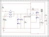
I'm a complete electrical novice (biomed background), and I have a query I'm hoping someone here can clear up. Anyway, I had to design a surgical instrument that required the use of a motor, however, said motor required a soft start circuit which a member of our technical staff built for me (saved my ass).

The guy who built it for me is away on hol, and I need to explain how the circuit works, but I'm at a loss as to how this is. Would anyone here be kind enough to explain not in complete laymans terms, but simple enough for someone with a minor electronic background, how the attached circuit works, please?

Thanks in advance.
 

Attachments

  • circuit.jpg
    circuit.jpg
    45.1 KB · Views: 779
The high value 1M resistor R2 charges the fairly high value 10uF capacitor C1 slowly so its voltage rises slowly. Then the output voltage of the opamp rises slowly so the motor starts running slowly.
 
Crap, sorry. I should have mentioned that the motor is required to either rotate clockwise, counter-clockwise, or remain stationary. That 3 switch mess you see in the image is my attempt at "quick-fix" for a SP3T switch, which I didn't know how to create virtually (zero SPICE experience prior to this week).
 
Thanks, AG. So would I be correct in saying the two following things:-

1) The Op-Amp output cannot exceed its input voltage.

2) The capacitor is charged non-linearly, but the Op-Amp amplifies voltages linearly.

Can you also explain the need for Zener diodes Z1 and Z2 and diodes D1 and D2?
 
The switch J3 starts the motor running in one direction slowly.
The switch J2 slows the motor to a stop quickly.
The switch J1 slows the motor to a stop slowly, then the motor starts running backwards slowly.
 
The switch J3 starts the motor running in one direction slowly.
The switch J2 slows the motor to a stop quickly.
The switch J1 slows the motor to a stop slowly, then the motor starts running backwards slowly.

Thanks, in reality the J switches are one SP3T switch so that you can't rotate a motor in the opposite direction without first quickly discharging the capacitor. Do you know the answer to my question about the Z Zener diodes and D diodes? Thanks again.
 
1) The Op-Amp output cannot exceed its input voltage.
No.
It is an amplifier so of course its output exceeds its input. It has a voltage gain of 10.1.

2) The capacitor is charged non-linearly, but the Op-Amp amplifies voltages linearly.
No.
The capacitor charges exponentially and the opamp output is the same because it is not an integrator. The opamp is a very simple amplifier.

Can you also explain the need for Zener diodes Z1 and Z2 and diodes D1 and D2?
The zener diodes prevent C1 from charging more positive than +5.3V or more negative than -5.3V so that it doesn't take too much time for something to happen when the switch position is changed.

The diodes prevent the high voltage produced from the motor when it is turned off (due to its inductance) from destroying the output of the amplifier.
 
Thanks so much AG, brilliant help. I meant to originally say "The Op-Amp can't exceed the supply voltage" (that was just a typo, i swear lol), is that correct?

Also, can you explain where you got the value of 5.3 V from? I'm not doubting you (it's obvious you know your stuff), it's just I need to be prepared incase someone poses the exact same question to me.
 
The output of most opamps cannot be closer than 1.3V away from the supply voltages.

The zener diodes are 4.7V when reverse-biased. They are in series with a forward biased diode (0.6V at the low current) because the polarity of the zeners are opposing.
4.7V + 0.6V= 5.3V.
 
The output of most opamps cannot be closer than 1.3V away from the supply voltages.

The zener diodes are 4.7V when reverse-biased. They are in series with a forward biased diode (0.6V at the low current) because the polarity of the zeners are opposing.
4.7V + 0.6V= 5.3V.

I just went through this. The 4.7V Zeners will be lucky to have a drop of ~4.2V at such a low (limited by the 1meg resistor) bias current. Zeners do not have a sharp knee at such low bias currents...
 

Attachments

  • F51.png
    F51.png
    34.1 KB · Views: 217
Last edited:
I just went through this. The 4.7V Zeners will be lucky to have a drop of ~4.2V at such a low (limited by the 1meg resistor) bias current. Zeners do not have a sharp knee at such low bias currents...
I notice that you selected a 1N4732 zener diode that is 4.7V only when its current is a whopping 53mA.
I would use the 1N4688 that is 4.7V with a current of only 50uA.
 
I notice that you selected a 1N4732 zener diode that is 4.7V only when its current is a whopping 53mA.
I would use the 1N4688 that is 4.7V with a current of only 50uA.

Yeah, AG, the circuit I posted was only my recreation in a SPICE program with the available components. So, while the theory of the circuit I posted is correct, the specs are incorrect, but I just wanted to know how you worked out the previous voltage values so I better understood the theory.
 
The diodes prevent the high voltage produced from the motor when it is turned off (due to its inductance) from destroying the output of the amplifier.

Hi, can someone explain the above statement a bit more in depth, please? I understand nearly all the functions now (thanks, AG!), but it's just this one part that has my stumped now. Damn my lack of electronics!
 
When the current in an inductor is turned off, the magnetic charge is still there but suddenly has nowhere to go, so it produces a high voltage spike which might arc across it and discharge it. But it will zap an amplifier driver if the inductor does not have a diode across it to discharge it.

The high voltage for the spark plugs in a car has the current in the spark coil disconnected and uses the high voltage spike. The high voltage for a TV's CRT is also produced from the spike of an inductor having its current turned off.

If you don't believe me then take a little relay and a new 9V alkaline battery. Hold both wires of the relay's coil in one hand (so you don't zap your heart) then connect the coil to the battery then disconnect it. ZAP!
 
Thanks again, AG. I think I half understand that, but why are the diodes both in the same direction? I mean, why are the diodes placed like that at all? I have a feeling that is a completely dense question, but I think I've given a fair estimation of my electronics n00bness already, so might as well commit myself now lol.
 
why are the diodes both in the same direction?
Since the motor can run forwards or backwards then it can try to produce a positive voltage spike or a negative voltage spike.
One diode clamps the voltage when it is positive and the other diode clamps the voltage when it is negative.
 

Attachments

  • protection diodes.PNG
    protection diodes.PNG
    17.1 KB · Views: 164
All I can say is that I hope you have a job in a university or some form of academic facility; you actually made this make sense for me lol. Thanks for the 20th time.
 
I am a retired old geezer. I will be 65 years old on Sunday. Then my government will give me lots of goodies.

I finished my electronics job 10 years ago and I went to school a long time ago.
I learned a lot in my career and am learning more on these electronic chat forums.
 
Status
Not open for further replies.

Latest threads

New Articles From Microcontroller Tips

Back
Top