Continue to Site

Welcome to our site!

Electro Tech is an online community (with over 170,000 members) who enjoy talking about and building electronic circuits, projects and gadgets. To participate you need to register. Registration is free. Click here to register now.

  • Welcome to our site! Electro Tech is an online community (with over 170,000 members) who enjoy talking about and building electronic circuits, projects and gadgets. To participate you need to register. Registration is free. Click here to register now.

Snubber power handling requirements

Status
Not open for further replies.

solis365

New Member
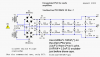
I have an application circuit I am attempting to use. There is a small series RC shunt between the output leads, which I am assuming is a snubber. I am not sure what power rating I should use for the resistor. Clearly, the capacitor should be rated higher than the maximum output voltage of the amplifier, so say 4/3 or 5/3 times Vcc, so at least 35V. Should I go for more voltage, as this is meant to suppress high-voltage transients? What sort of power dissipation am I looking at for the resistor?
 

Attachments

  • la4282 application circuit.GIF
    la4282 application circuit.GIF
    23 KB · Views: 2,238
Last edited:
Your mysterious "application circuit" looks like a stereo audio amplifier. (You didn't say what the circuit was for, so I had to guess. Was that a test?:rolleyes:) If so, the RC circuit is not a snubber (in the usually sense of the word to suppress transients) but provides a high frequency rolloff to stabilize the amp against the high frequency inductive impedance effects of a typical speaker. As such the dissipation in the 2.2Ω resistor is essentially zero.
 
Hi,

Have used other similar ic amps, the c / r network you mention are used, quote datasheets ' for frequency stability '

Typically the resistors are 1 or 2 watt versions and the capacitor 63v Polypropolene or Polyester
 
Ah yes, I meant to state what it was for but got distracted while writing... Sorry about that, you are correct. Stereo audio amplifier. Thanks for clarifying. I was afraid I would have to order some power resistors or something.

However, I am still curious about snubber circuits in general.
What kind of power do you have to rate them for? Say you were using them for an unregulated supply, as in the circuit at the top of this page?
**broken link removed**
The picture is also attached in case that website goes down and someone years in the future searches and finds my thread ;)

The schematic says 2W for the resistor, is this just a safety margin or can 1-2W spikes really be expected from a power supply of this size?
 

Attachments

  • Snubberized PSU.png
    Snubberized PSU.png
    19.7 KB · Views: 508
Last edited:
Hi,

Have used other similar ic amps, the c / r network you mention are used, quote datasheets ' for frequency stability '

Typically the resistors are 1 or 2 watt versions and the capacitor 63v Polypropolene or Polyester

Such high ratings even for a small 10W amp like mine? I dont even think the chip is 10W/ch, I think its 10W total. My supply voltage is at most 24V.
 
However, I am still curious about snubber circuits in general.
What kind of power do you have to rate them for? Say you were using them for an unregulated supply, as in the circuit at the top of this page?
**broken link removed**
I'm sure Carlos can sell you some Oxigen-bearing copper wire for your speakers, too. As always, just because it appears on some web site doesn't mean that it has any scientific or engineering merit...
 
Such high ratings even for a small 10W amp like mine? I dont even think the chip is 10W/ch, I think its 10W total. My supply voltage is at most 24V.
As I stated the RC circuit is just for stability and the resistor power dissipation for normal music output is negligible. A 1/4W resistor should be fine.
 
Say you were using them for an unregulated supply, as in the circuit at the top of this page?
**broken link removed**
Pure hokum from Carlos. It's truly amazing what some "audiophiles" will believe helps improve the sound. I've seen $1000 filtered power cords which they claim, with a straight face, clarifies the sound from their $10,000 tube amp which, of course, is already greatly superior in sound to that from solid-state amps.
 
Looks like output compensation to me.
This network is very common in amplifiers, especially monolithic bricks that use a lot of feedback. The amplifiers need a guaranteed load at high frequencies in order to be unconditionally stable. The network power requirements are very small.

I agree, a 10W amplifier should be able to use a 1/4W or 1/2W resistor. But do not use a loose tolerance electrolytic for the cap; its value is important.
 
thanks for the clarification mneary and crutschow.

as for the audiophile bashing, I am well aware of the hocus pocus that goes on. however I am not talking about thousand-dollar filtered power cables. I am talking about a ten cent capacitor and a ten cent resistor. the schematic I posted was a simple rectifier and reservoir cap power supply. snubbers are used in other areas of electronic design, it would make sense to at least try them on an audio power supply to suppress transients. it might not work to improve sound but its under a dollar of parts. and yes the guy talks about sparkling highs and magical mids on his webpage, so I take it with a grain of salt. I can't hear above15kHz anyway.

the schematic provided was meant as an example of a snubber being used. I meant my question in a general sense - i suppose it would depend on the specific transients in my hypothetical system, but if I were getting unwanted spikes in a circuit like that (psu capable of say 200W, powered from wall), what sort of spikes might I expect, and what's a good rule of thumb for rating snubber parts appropriately? try and look at the spike with a scope, estimate the average power in one transient, and based on the duration and frequency of occurrence of the transient pick a resistor and cap that can handle it?
 
The "snubber" on the amplifier output is called a Zobel by some, although others would only call it Zobel if it's designed with a particular speaker in mind. I seldom see it named "snubber". These networks on the output also help tame RF picked up on speaker lines.

In an audio amp, unwanted spikes are unlikely to be found across tens of thousands of microfarads of filter caps. That's why the "snubberized" power supply attracted such ridicule.

A snubber might be required (but absent) across the main power switch or relay. This shortcut can make popping noises when turning off, and can affect switch life.

Some receivers use small caps, sometimes snubbers, across the diodes in their big rectifiers. This can keep EMI out of their own AM and FM tuners and has little to do with audiophile quality, unless you're an audiophile listening to AM.

Snubber-like networks are often employed as RF countermeasures on poor preamplifier designs that otherwise would pick up radio interference.
 
Last edited:
The "snubber" on the amplifier output is called a Zobel by some, although others would only call it Zobel if it's designed with a particular speaker in mind. I seldom see it named "snubber". These networks on the output also help tame RF picked up on speaker lines.

In an audio amp, unwanted spikes are unlikely to be found across tens of thousands of microfarads of filter caps. That's why the "snubberized" power supply attracted such ridicule.
...

Agree 100%. Snubbers are employed to suppress transients at their SOURCE, usually inductive loads like Relay Coils, Solenoids, Motors, alternator field windings, and maybe even speakers. You could think of the RC network across the speaker leads as being a "snubber", but it is actually tailored to dampen "high frequency peaking" due to the feedback in the audio power amplifier. The design criteria for the speaker damping is not the same as a transient-suppression snubber .

The RC network across the output of the unfiltered power supply shown does nothing, is totally unnecessary, and takes up board space. Claiming that it is needed, or that it "improves sound" casts doubt that the author of the original circuit knows what he/she is doing, and makes me skeptical of ANY claims made for the rest of the circuit...
 
Some receivers use small caps, sometimes snubbers, across the diodes in their big rectifiers. This can keep EMI out of their own AM and FM tuners and has little to do with audiophile quality, unless you're an audiophile listening to AM.
The caps across the rectifiers work by cushioning the abrupt turn-on of the rectifiers when they are rectifying AC power. This fast turn-off can generate high frequency harmonics of the power frequency when can find their way into the AM or FM circuits and cause an audible buzz.
 
Last edited:
Status
Not open for further replies.

Latest threads

New Articles From Microcontroller Tips

Back
Top