Venkateszr
New Member
Newly designed 5v 1A smps output drop 200mA load connected to it. No load condition it show 5v. When load is connected drop to 3v.
How to fix it?
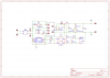
P1&P2_Input 240v AC
P3&P4_Primary Winding
P6&P5_Auxiliary winding
P7&P8_Secondary Winding
P9&P10_Filter capacitor 10uf,400v
P11&P12_Output 5v 1A
Switching IC is AP8012 Not VIPER 22A
Circuit Attached here
How to fix it?
P1&P2_Input 240v AC
P3&P4_Primary Winding
P6&P5_Auxiliary winding
P7&P8_Secondary Winding
P9&P10_Filter capacitor 10uf,400v
P11&P12_Output 5v 1A
Switching IC is AP8012 Not VIPER 22A
Circuit Attached here