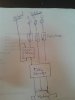
Do you have snubbers across both the motor and the starter contactor coil?
A contactor coil can produce a massive voltage spike when switched off, which may have arced between your relay contacts and other components.
Most control gear makers have snubbers that fit to their contactors, or you can buy generic wire leaded ones - eg. 100 ohms and 0.1uF in series are a common type.
eg. a Telemechanique / Schneider one that clips on one series of contactors:
**broken link removed**
A range of generic types for such as contactor or solenoid coils
https://uk.rs-online.com/web/c/passive-components/capacitors/rc-network-capacitors/
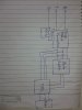
An example for three phase motor suppression:
https://uk.rs-online.com/web/p/surge-suppressor-units/0240400/