ejazbeyond
Member
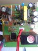
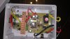
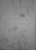
We are using a smps for our comm pcb , a relay and a current sensor, which uses 4.2v, 12v and 5v respectively. We are controling one phase of a three phase 5hp water motor. Also smps circuit and relay output are in parallel so output load doesnt effecting our smps. Problem is when we tested our complete device in lab on a room heater of 2kw its working fine however when tested in field on dol starter type 5hp motor our device fuse(3A) and transistor s9014 and s8550 blown up.