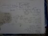
I am working on a 30 V 20 A SMPS. Following is the specification-
I/P - 180 VAC to 250 VAC.
Output - 30 V/ 20 A with current limit.
Configuration - Full bridge.
Frequency - 85 kHz.
Control method - Voltage mode using SG3525A.
DC blocking capacitor -1.5 mfd.
Transformer - EE42/15 core (EPCOS) with 27: (6+6) turns ratio.
O/p inductor - 20 micro henry.
O/p Capacitors - 4x2200 mfd 35 V general purpose 105 deg. C.
I/p capacitors - 2x330 mfd 450 V general purpose 105 deg. C.
What should be the type of the DC blocking capacitor? I am using VISHAY MKP1839HQ type. Will this do?
The problem I am facing is as follows-
Upto around 16 Amps of current the system works OK. Above that current the circuit starts generating noise after operating for around 10 seconds. If I keep the circuit ON after that, the MOSFETs (12N60) blow. I hv not included the current limit circuit yet.
Pls note that the stability network is type II, but the stability components are selected based on trial and error method, as the calculated components are not solving the problem of instability.
The feedback and control network is based on the secondary side and the MOSFETs are driven through optocoupler 6N139 and IR2110.
Can anybody pls help in solving the problem?
regds,