Continue to Site

Welcome to our site!

Electro Tech is an online community (with over 170,000 members) who enjoy talking about and building electronic circuits, projects and gadgets. To participate you need to register. Registration is free. Click here to register now.

  • Welcome to our site! Electro Tech is an online community (with over 170,000 members) who enjoy talking about and building electronic circuits, projects and gadgets. To participate you need to register. Registration is free. Click here to register now.

Smps 12 to ~ 30

Status
Not open for further replies.

kinarfi

Well-Known Member
I have tried several schemes and just not having good luck, sometimes it works but not exactly what I need, yada yada, maybe it my choice of inductors or my lack of understanding intricacies of inductors. Here's some I have salvaged out of some server power supplies and the measurements I got, I need to make 30 volts and 2 amps out of 12.5 to 14.4 that can be switched to 18.5 volts and upto 3 amps by switching the feed back scheme and I'm hoping someone can suggest the correct inductor to use maybe guess at the specs on the ones in the pictures. May someone can explain why the smaller red inductor has a reading almost time the bigger red one. Same question about the 270uh inductor, or did I mis-measure the 30uh inductor?
Thanks,
Kinarfi
 

Attachments

  • IMG_0001.JPG
    IMG_0001.JPG
    3.4 MB · Views: 1,102
  • IMG_0002.jpg
    IMG_0002.jpg
    1.4 MB · Views: 201
I have written an article on switched mode power supply design, especially boost converter design and how the switching frequency and inductor value are related. This will help you understand what is going on:
http://www.simonbramble.co.uk/dc_dc_converter_design/dc_dc_converter_design.htm

It is all simulated in LTSpice, which I recommend to get your head around the basics. See my LTSpice tutorial:
http://www.simonbramble.co.uk/lt_spice/ltspice_lt_spice.htm

People make SMPS design out to be much more complex than it is. Once you get your head around how the current in an inductor changes with voltage, the rest is just high school geometry
 
Other points to note: without looking at the datasheet of the chip and getting my calculator out, I would have said that your output capacitor value needs to be at least 100uF. Your load is probably draining the output cap before the inductor has had a chance to top it back up again. Also, DO NOT leave your feedback pin floating - or disconnected from the output. Your chip will think that the output voltage is at zero and work like billy-o to increase it - this might have the net effect of blowing up all your output components. If you want to tweak the ouptut voltage, change the 1k resistor on the bottom of the FB chain to 2 resistors and make one of them adjustable
 
Thank Simon, Got your stuff downloaded already, now I've read it.
I've kind of been working on this like a man driving a truck in the forest, I don't need no map!!!!! Well I'm reading the maps now and going to try it that way, will rebuild one of my inductors to match what I think I need by removing a few turns and see what happens.
Any good reasons of the differences in the inductors?
Kinarfi
 

Attachments

  • 1400ma LED Driver 3.png
    1400ma LED Driver 3.png
    70.8 KB · Views: 582
There is really no difference in using one inductor over another. The smaller the inductance value, the faster the frequency the part will switch at. Looking at your inductors, the size of them looks like they can handle the current. Try any of them and see. From V/L = di/dt, your duty cycle with the voltages shown should be 55%, so your ripple current will be 1.13A. It looks like all of your inductors should be able to handle this.
 
I need some help, some advice or someone to design an SMPS that works for 12.6 - 14.4 volts from my vehicle to drive 2 20 watt LEDs in series, each rated at 12.5 volt, 1500 ma so I need aprox 30v because I am limiting the current with 1.5 amp LM317 circuit that needs about 3.5 volts.
I have tried 555s, L296, and a few other chips. I am currently trying to get a TPS40211 to work. I tried to copy the design in the spec sheet, with some changes and I can get it running, but as I raise the input voltage, it quits at about 10v and I have to turn the input voltage down and back up to get it to restart, and I can not get the voltage high enough to drive the LEDs at the proper current.
attached is the drawing I'm working off of with the changed values.
data sheet https://www.electro-tech-online.com/custompdfs/2011/07/tps40210.pdf
If wanted, I can get some scope shots too.
Thanks,
Kinarfi
 

Attachments

  • Keep Trying.png
    Keep Trying.png
    110.8 KB · Views: 267
One of my problems was these things are sooooo small, and I'm not as nimble as I once was. I think I got the problem liked though, found a DIP8 MC34063A and it worked on the first attempt. Maybe I have learned enough from my failures, but I think this is just a simpler chip. I basically used their schematic with an NFET instead of a NPN transistor.
I appreciate your help and advice, it seems there are as many smps chips out there as the there were different transistors back when I graduated from Electronics school in 1970, the red LED was brand new then, and I'm having the same problem now as then, which one matches my needs the best. which is better? a 2N2222 or a 2N4400 or a 2N4401? I had 2N4401 to work with in school and I still use them, don't think I've ever used a 2N2222, I'm sure it's a good unit. Now it's finding the best smps chip, but I have to do most of my own research and testing, with some help from forums.
Any way, I hope what I have now works for me, needs tweaking and I'll probably post the schematic when I'm done
Thanks for the help,
Kinarfi
 
Last edited:
got it finished, installed and it works very well, now for a 13.6 to 18.5 v up to 3.5 amp smps using TPS40210 or TPS40200
Kinarfi
 

Attachments

  • MC34063.PNG
    MC34063.PNG
    82 KB · Views: 392
I agree, just got to get all the parts together, Is there a site that has the specifics for winding your own inductor? for instance, if I remember correctly, the impedance of coax depends on dielectric, dielectric thickness, center wire diameter, shield diameter, etc.
Thanks
Kinarfi
 
Hi,

Winding your own inductor isnt that easy. You have to know what kind of core material you have first, and how many turns you can get away with at a certain DC current (for a switching power supply application) before it saturates. This means many times you would need to introduce a gap, and gaps of the correct width are not that easy to make in most cores unless they come in two halves or you have an E I type core.
This is why most people simply purchase their inductors already wound. The idea is to figure out how much inductance you need, how much DC current it has to handle, then look online for an appropriate inductor.

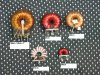
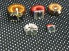
I've wound several of my own inductors in the past using various methods and even ones that weight in at over 100 pounds each. I use several formulas that tell me what is what, but the hardest part i have found is when you happen to already have a ferrite toroid core (or similar like your pictures) and you do some calculations and find out that it will saturate with the required DC current once you get the correct number of turns to achieve the correct inductance. If you can introduce a small air gap you can increase the cores ability to handle the DC current and possibly get this thing to work, but the real problem is how do you make a core in a toroid without breaking it? Companies that make cores like this have very expensive equipment to do stuff like this, but we dont usually have access to that unless we work for that company. You can use a Dremel and diamond cutting wheel but in most cases you'll get a gap that is too wide. Another option i've tried with some success is to break the core on purpose in a vise, with the core wrapped in a rag. With very gentle pressure, you can get the core to break in more or less 4 pieces of about equal size. You can then glue them back together with some good high temperature glue and that gives you a fairly narrow gap.
Since the introduction of a gap reduces the core overall permeability, another approach is to start with a lower permeability core. That might get you there too.

So you can start to see some of the problems you run into when you want to wind your own core. It's not just a matter of getting a core and winding some turns and testing, then winding some more turns and testing, the more turns etc., because although doing it that way gets the inductance to increase with each new added turn, it also reduces the ability of the core to handle DC current with each new turn, so you get an advantage in inductance with each new turn but a disadvantage in lower DC current handling with each new turn.

One of the coolest things that comes from this though is when you think about the entire design you start to realize that there is yet another constraint that comes up. That is the fact that a certain size toroid core can only handle a certain number of turns through the center opening. This led me to a program that draws the core so i could get a visual on it as well as figures out how many turns will really fit. I'll post a few interesting pics. These pics shown below are from a program that 'winds' the toroid the same way a human would do it, showing the inner core opening cross section after it's wound. The little circles are the wire cross section and the large circle is the core opening in the center.
 

Attachments

  • NEWBIM0065.gif
    NEWBIM0065.gif
    10 KB · Views: 186
  • NEWBIM1080.gif
    NEWBIM1080.gif
    40.8 KB · Views: 173
  • NEWBIM4328.gif
    NEWBIM4328.gif
    55.2 KB · Views: 167
Last edited:
Thanks MrAl,
https://www.electro-tech-online.com/attachments/img_0001-jpg.55629/
Using the previously uploaded picture, I was wondering about the construction "physics" of inductors, why is the center top inductor only 30uh with 15 turns and the lower left is 270uh with only 12 turns, and the top right is only 308uh and has many more windings. Is it the cross section area of the core, the permeability, or what, that's info I'm trying to find access to.
Any suggestions as to where to look?
Thanks
Kinarfi
 
Last edited:
Is it the cross section area of the core, the permeability
Yes, among other things! Try Googling for tutorials about inductance, or your local library may have a suitable textbook.
 
Thanks MrAl,
https://www.electro-tech-online.com/attachments/img_0001-jpg.55629/
Using the previously uploaded picture, I was wondering about the construction "physics" of inductors, why is the center top inductor only 30uh with 15 turns and the lower left is 270uh with only 12 turns, and the top right is only 308uh and has many more windings. Is it the cross section area of the core, the permeability, or what, that's info I'm trying to find access to.
Any suggestions as to where to look?
Thanks
Kinarfi

Hi again,

Yes, the permeability of the core material is the key factor here. Permeability is usually represented by the Greek letter (pronounced as) 'mu', sometimes represented by the lower case English 'u'.
A higher mu core will exhibit higher inductance per turn than a lower mu core, so you'd measure a higher inductance with a high mu core and lower inductance with a lower mu core. That's the advantage of a high mu core. The disadvantage is a high mu core can not handle DC current as well as a low mu core for materials that have about the same saturation level.
The permeability acts like a multiplication factor for multiplying the applied field (which comes from the applied current) which means more inductance within the non saturation region. So you can get a physical construction that has more inductance with less turns if you use a high mu core material, but less ability to handle DC current.

The air gap if present acts to make the core magnetic path length seem longer, so with an air gap we get less inductance but better DC handling capability. It's a tradeoff, higher inductance vs DC current handling ability.
 
Last edited:
Status
Not open for further replies.

Latest threads

Back
Top