Continue to Site

Welcome to our site!

Electro Tech is an online community (with over 170,000 members) who enjoy talking about and building electronic circuits, projects and gadgets. To participate you need to register. Registration is free. Click here to register now.

  • Welcome to our site! Electro Tech is an online community (with over 170,000 members) who enjoy talking about and building electronic circuits, projects and gadgets. To participate you need to register. Registration is free. Click here to register now.

SMD Diode Identification

Status
Not open for further replies.

JimG48

New Member
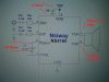
I am repairing an iLive IBB683B Boombox. I have isolated the problem to diode D9. The markings on the diode are:

Upper Left "IR"
Upper Right "3C"
Middle "P308L"

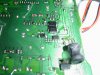
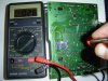
Can anyone help me identify this part. I have looked everywhere with no luck. the size of the diode is approximately 5mm x 6mm. Maybe an SMC package.
see pictures. Two diodes in the center are the ones I am looking for. Thanks.
 

Attachments

  • DSC00068.JPG
    DSC00068.JPG
    1.3 MB · Views: 247
I did a basic resistance check in each direction. I get 250 ohms in each direction. The other diode of the same type behaves normally. High resistance in one direction and lower in the other. I think these may be Schottky diodes used to protect the lithium battery from reverse polarity/current. They seem to be in the charging circuit. They are near a TP4506 chip which is a battery charging IC. The radio appears to be working. The clock lights and when I am in FM mode the LCD displays the changing bar graph but I get no sound. I think the battery may be gone because it does not charge. Typical for a battery that wasn't charged in a long time.
 
That little black thing is is only kerplunk when it is zero ohms in both directions.
Not necessarily. I have had diodes fail with a "soft short" many times. They would often measure between 10 ohms and 400 ohms. I'm sure the range would grow if I tested a larger sample size.

JimG48 Use the diode function of a multimeter. That should work in-circuit to identify whether or not the diode has actually failed. The 250 ohms may be coming from elsewhere in the circuit. Either that or desolder the diode and test it out-of-circuit, but even then the diode test is better than a resistance test.
 
DerStrom8 Thanks for the response. I tried the diode function on the meter. It seems to give me the same results as the resistance test. Not sure why. I misspoke before. The reading I get is 25 ohms in each direction. I am pretty sure the diode is hosed. The real question is what to replace it with.
 
The diode test does not measure resistance, it measures voltage drop. A good diode will usually drop either 0.3V or 0.7V (maybe higher for high-power diodes or Zener/TVS diodes). What exactly did your diode test function display when you connected the probes across the diode in each direction?
 
I thought that was the case. I am using an old Sears 82416 meter. In the diode test mode i still read 025 in either direction. I guess 25mv? I tried another meter and I get the same result in diode mode. The other same type diode measure 172 in one direction and 656 in the other. That one I think is good.
 
I thought that was the case. I am using an old Sears 82416 meter. In the diode test mode i still read 025 in either direction. I guess 25mv? I tried another meter and I get the same result in diode mode. The other same type diode measure 172 in one direction and 656 in the other. That one I think is good.
Those numbers mean nothing. Where is the decimal point? There should also be an indication of the units on the meter's display. Please post clear photos of the multimeter display while performing these tests.
 
Sorry for the confusion. Those are the readings I am getting. There is no decimal point. I assume the units are millivolts. 0.025 volts in both directions for what I think is the bad diode. I checked a 1n4001 out of circuit to see what I get for measurements. Positive lead to anode and negative to cathode i get a reading 612 millivolts or .612 volts. Exactly what you would expect for a good diode. I attached a picture showing the 025 reading. In fifty years of repairing electronics, I have never been wrong assuming a bad diode with the readings I am getting. I suppose there is always a first time.
 

Attachments

  • DSC00070.JPG
    DSC00070.JPG
    1.3 MB · Views: 164
Unsolder it, replace the battery with a fully charged one and tack the 1N4001 in place to see if it comes to life. If it does, unsolder again and measure the current across the pads to choose a suitable replacement.

Mike.
 
Ok, that's not the meter I was picturing. That explains a lot.

Definitely pull the suspected diode and test it using the diode test out of circuit. We can go from there.
 
Thanks. I will remove and tack in a substitute with a new charged battery to see what happens.
I'm talking about measuring the suspect component itself out of circuit. I wouldn't put in a replacement on the board yet - first confirm that the part you have is bad.
 
I will check the part when I take it out to make sure that it is bad. I will let you know what I find before i do anything else. If the diode is there for UL reverse polarity protection it is not critical for the operation of the radio. I am thinking the radio should run fine off a charged battery without the bad diode in there.
 
That is true if the diode is across the supply, if in series then it wont work.

Mike.
 
Sounds like a transient voltage suppression (TVS) diode. If there was a power surge (or the wrong supply was plugged in) it could have damaged the diode and caused it to fail short-circuit. Taking it out of the circuit should allow you to test it with your ohmmeter and also allow you to test your board again without the diode installed. Just use a current-limited supply if you have one available.
 
Okay I was wrong. It wasn't the diode. Good catch Dersrom8. I should have listened to you. Prior to removing the diode I decided to probe around some more and I found some strange readings around the left audio amplifier chip. It is a NSIWAY NS4160. See attached circuit diagram. I was able to disconnect the power to the amplifier chips by disconnecting a convenient jumper. Once I did that, the diode acted like a diode again. So it appears that the problem is in the left audio amplifier circuit. I annotated the drawing with the readings I am getting. The ones I think are strange are the 26 ohms across Capacitor Cb and the 2 Ohms across the source to ground capacitor. Both are small SMD caps which I have had problems with on other repairs. They usually short out completely though. Any thoughts on whether it is one of the caps or maybe the chip itself? The right side amplifier has a good reading across Cap Cb. The other readings on the right are the same as noted on the diagram.
 

Attachments

  • DSC00073.jpg
    DSC00073.jpg
    426.4 KB · Views: 147
Status
Not open for further replies.

Latest threads

New Articles From Microcontroller Tips

Back
Top