Continue to Site

Welcome to our site!

Electro Tech is an online community (with over 170,000 members) who enjoy talking about and building electronic circuits, projects and gadgets. To participate you need to register. Registration is free. Click here to register now.

  • Welcome to our site! Electro Tech is an online community (with over 170,000 members) who enjoy talking about and building electronic circuits, projects and gadgets. To participate you need to register. Registration is free. Click here to register now.

Simulation model for the LM3915 logarithmic bar/dot display driver

Status
Not open for further replies.
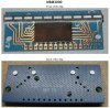
My model uses only arbitrary behavioral current sources, a standard voltage source, standard resistors and diodes. So far as I know these are all generic devices present in various flavours of Spice, so not proprietory. I can't speak for Multisim, though.
 
I see the question of importing LTSpice files over to multisim a lot, even on the Multisim Forums. I have Multisim 14 base version, so I may give this a try. I will let ya know :)
 
I know that this is an old thread, but it seems to be the best one for LM3914! I have been trying to get a simulation to work for a while, but it is sort of giving me the opposite effect of what I expected the LM3914 to do. The attached picture shows the first 2 diodes and that they start high and then drop low. What do you make of this? I assume that I am doing something stupid based on my lack of knowledge of LTSpice, but I have been spending hours on this and can't seem to get it right. Any help would be appreciated!!
 

Attachments

  • plot.png
    plot.png
    46.9 KB · Views: 229
I suggest you study the datasheet for the IC and any Application Notes you can find.
Try increasing R2a (e.g. to 1k2). This affects the range of reference voltages used by the comparators inside the IC.
Please post your .asc file.
 
Last edited:
I suggest you study the datasheet for the IC and any Application Notes you can find.
Try increasing R2a (e.g. to 1k2). This affects the range of reference voltages used by the comparators inside the IC.
Please post your .asc file.
Thanks. I had been running with 1k2 for a while, but at aome point I changed it. I changed it back and it isn't any better. I attached the asc, sorry I didn't do that to begin with,
 

Attachments

  • LM3914_Test_JJM.asc
    2.4 KB · Views: 228
With R2a low, all the comparator reference voltages will be close to 1.2V, but your input signal voltage is a fixed 12V (not ramped at the moment) so in Bar Mode all LEDs should be on if your LED model is working correctly.
For now, I suggest you just use the default diodes instead of the model ones.
I don't know what you are trying to achieve, but if you want to see the LEDs come on in sequence then do a transient analysis instead of a DC one, increase R2a to ~12k, set a rise time for the V3 source, and remove the Bar/_dot pin connection so that the IC operates in dot mode.
 
OK, I got it working, it was my issue (as I suspected). For some reason (I recall doing it, but not sure why), I went in and changed the LM3914.sub file so that the Rhi and Sig pins on the .subckt line were swapped..... Once I discovered that, I swapped them back to the way they should be, and low-and-behold, everything functions as you designed them to!

Thanks again for looking into it, and for designing it in the first place! It is truly the only model that exists out there it seems!
 
RIP, LM3915 :(.
 
I have some old National Semi NSM3900 modules with an LM3915 COB and an LED strip.
 

Attachments

  • NSM3900-1.JPG
    NSM3900-1.JPG
    84.3 KB · Views: 211
LM3914 are still listed by Digikey (and no doubt other distributors), albeit only in the PLCC package.
 
Didn't you know that the 30 years old LM3915 is now obsolete and is not made anymore? You might find somebody selling used or fake ones.
 
Status
Not open for further replies.

Latest threads

Back
Top