Continue to Site

Welcome to our site!

Electro Tech is an online community (with over 170,000 members) who enjoy talking about and building electronic circuits, projects and gadgets. To participate you need to register. Registration is free. Click here to register now.

  • Welcome to our site! Electro Tech is an online community (with over 170,000 members) who enjoy talking about and building electronic circuits, projects and gadgets. To participate you need to register. Registration is free. Click here to register now.

Simulation Circuit of DC-DC Voltage Mode Boost Converter

Status
Not open for further replies.

ching94

New Member
I am HongKonger and here sorry for my poor English.

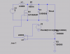
I am doing the school project which is basic voltage-mode boost converter for 5VDC input transformed to 20V at ~25mA for a series of LEDs.

Honestly, I am newbie to Power Electronics. Although i know the basic operation of Boost Converter; when the transistor switch is turned on , the power source cha capacitor is charged by corge up the inductor through the switch, whilist the capacitor discharges to load. hen transistor is turned off, thembined voltage which include power source and inductor, also the load. But i don't know how to build up the discrete circuit with exact components.

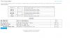
I have done some research and found calculator for evaluating the value of components.

Thanks!.
 

Attachments

  • circuit.png
    circuit.png
    173.3 KB · Views: 161
  • calculator.jpg
    calculator.jpg
    152.9 KB · Views: 159
Welcome to ETO!
Consider the following :
1) The LM339 has an open collector output, so needs a pull-up resistor.
2) FETs need to transition rapidly between the on and off states, otherwise they heat up.
3) The gate capacitance of the FET has to be charged and discharged, which takes time. The time should be minimised by using low-resistance driver circuits.
4) The gate turn-on threshold, Vto, for your chosen FET is 2.9V. At that voltage the FET will conduct only microamps. It needs a gate voltage significantly higher to conduct significant current. 5V may not be high enough.
5) R2 and R3 have impractically high values. You could reduce them by two or three orders of magnitude.

Your schematic is hard to read because of all the zeros. Instead of 0.000005, for example, you could write 5μ or 5u.
 
In addition to what alec already posted, here is another suggestion:

To power LEDs, the controlling parameter is LED current; the LED forward voltage is a consequence of the LED current.

If building a step-up converter specifically to power LEDs, the control-loop should sense LED current, and the smps should keep the current through the LEDs constant. Your proposed design is a controlled voltage, which is not appropriate for powering LEDs.
 
You also need power to the 339.
 
Here is a circuit where:
Vin is about 5
Vout is about 19V but is not regulated.
Iout is 24mA and is regulated.
(so it is a current regulator not a voltage regulator)
Down load and run the .ASC file attached. (if you have LTSpice)
upload_2016-9-24_18-41-29.png
 

Attachments

  • 1937-LED-ron.asc
    2.6 KB · Views: 132
Sorry need to make a change. Can't see how to replace the files in last post.
upload_2016-9-24_18-47-37.png
 

Attachments

  • 1937-LED-ron.asc
    2.6 KB · Views: 123
Thanks for help of you. But my supervisor requests me using the voltage-controlled circuit with discrete component. He guides me using LM339 as comparator & there should be a DC level , ramp generator. How can i do. I don't have any idea. :arghh:
 
Unless
I use 1,000,000s of LEDs a year. They are current devices not voltage devices. You should not apply voltage to a LED.

So can you use ICs? Or just transistors?

I think it is difficult for the student who is beginning level to start with this.
 
...But my supervisor requests me using the voltage-controlled circuit ...
Then your supervisor has a lot to learn about how to use LEDs, and would not survive long in the real world of engineering.
 
"home work" so I should not do your work.
Do you know how a boost up circuit works?
>Your circuit from post #1. L1 is like a rubber band. (spring) If you hold the end up in the air 5cm (5 volts) and pull the other end down there is energy stored in the rubber band or spring. Let go of the bottom end and the rubber band flies up in the air. This is how a boost circuit works.
>This needs to happen many times to make high voltage.
>The IC I used has a transistor on SW that pulls the inductor to ground.
>There is an oscillator in side that makes the transistor turn on 1,000,000 times a second.
>FB looks at the current in the LED. If the current is too low it causes the current in the inductor bigger. If the LED current is too bit it makes the inductor current smaller.

If you are very clear on this we can move on to next step.
 
Search internet for "boost up circuit". There is a simple 3 transistor circuit. Very common.
Play with values to get some thing like this:
Q3, Q1 is an oscillator.
Then Q1 is on current in L1 ramps up.
Current is measured in R2. When voltage across R2 reaches 0.7V it will turn on Q2 which turns off Q1.
L1 shoots up making high voltage.
D8 is 20V Zenner diode. When the output voltage about 20V it will turn on Q2. (regulation)
upload_2016-9-24_20-23-36.png

Play with circuit. Look at voltages and current. Learn. Be able to explain how it works.
If you get circuit form internet and I help you this much you need to understand circuit very will.
 

Attachments

  • transistor-boost-ron.asc
    3.8 KB · Views: 124
But my supervisor requests me using the voltage-controlled circuit with discrete component. He guides me using LM339 as comparator
The LM339 is not a discrete component; it is an integrated circuit! You need clarification from your supervisor as to what you can/can't use for this assignment.
 
The LM339 is not a discrete component; it is an integrated circuit! You need clarification from your supervisor as to what you can/can't use for this assignment.

He said i could use LM339 as comparator and LM324 as compensator. The switch shall not be an IC, should a transistor.
 
The LM339 is not a discrete component; it is an integrated circuit! You need clarification from your supervisor as to what you can/can't use for this assignment.

I don't know how to start with the circuit.

e.g.: Value of R,L,C , model of component, wiring connection.

I thought i am gonna fail the project. :banghead::banghead:
 
I don't know how to start with the circuit.
Ron has given you guidance in post #12.
Your circuit needs an oscillator which can be turned off whenever the converter output voltage gets too high.
The comparator's job is to sense the output voltage and compare it with a reference. If the reference is exceeded the comparator turns off the oscillator. It turns the oscillator back on when the output voltage drops below the reference.
He said i could use LM339 as comparator and LM324 as compensator.
I don't know what he means by 'compensator' in this context.
 
Status
Not open for further replies.

Latest threads

New Articles From Microcontroller Tips

Back
Top