Continue to Site

Welcome to our site!

Electro Tech is an online community (with over 170,000 members) who enjoy talking about and building electronic circuits, projects and gadgets. To participate you need to register. Registration is free. Click here to register now.

  • Welcome to our site! Electro Tech is an online community (with over 170,000 members) who enjoy talking about and building electronic circuits, projects and gadgets. To participate you need to register. Registration is free. Click here to register now.

simulating an LM386 circuit

Status
Not open for further replies.

MrDEB

Well-Known Member
Found the file for SPICE but inserting into the LTSPICE program?
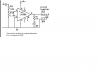
here is the circuit I am trying to figure out WHY I can hear 28khz sounds.
Using a 9v 200ma wall wart. When I used a 9v battery I couldn't hear any sound. Figure it must be V= related. When I change the input square wave to under 12khz I can hear the tone very well but above 12khz it sounds like its underwater.
Using a PIC to output the square wave.
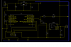
here is the schematic as well. I used slightly different caps but ?
 

Attachments

  • lm386 bat amp.png
    lm386 bat amp.png
    19.2 KB · Views: 529
  • bat circuit2.png
    bat circuit2.png
    34 KB · Views: 456
C5 and C6
Maybe need more?
I think c5 is 10uf elect and c6 is 1uf but would need to take unit apart again.
Plan is to use as is, build another unit and try again with different/ more PS caps.
You might be on to the solution. Never occurred to me.The PCboard didn't come out as planned, started having traces lift from the board. Thinking I got the board too warm when I laminated the toner transfer on.

Only the left hand graphic was there when I replied - but instability on IC amplifiers is common if the layout isn't good, and in particular close decoupling is a major help.
 
Am redoing the board with closer cap/Vdd,Vcc connections.
also larger caps perhaps.
Thinking of adding one on the LM3856 pins 6 & 4.
 
I used what I have but going to rebuild using a 10uf elect. on the 7805 input to ground sand .01 on the 7805 output to ground.
Adding a .01 across the amp power pins (6 & 4)
I feel the PCboard i made was not real good in the layout department. Caps too far away from pins and some raised traces (I think i got the board too hot when laminating. First time for everything.
 
Status
Not open for further replies.

New Articles From Microcontroller Tips

Back
Top