Continue to Site

Welcome to our site!

Electro Tech is an online community (with over 170,000 members) who enjoy talking about and building electronic circuits, projects and gadgets. To participate you need to register. Registration is free. Click here to register now.

  • Welcome to our site! Electro Tech is an online community (with over 170,000 members) who enjoy talking about and building electronic circuits, projects and gadgets. To participate you need to register. Registration is free. Click here to register now.

simple voltage detecting circuit

Status
Not open for further replies.

soadrage7654

New Member
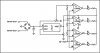
Hello. I am working on a simple circuit for determining the voltage output from a small hand-made windmill generator. The circuit uses an LM339 quad comparator to light up 1-4 LED's depending on how high the voltage from the generator is. But for some reason, the LED's are either all on or all off. Could someone look at the circuit and help me figure out what's wrong?

Before everyone goes crazy about you doing my homework, I would like to point out that the assignment does not require me to do this at all. I just thought it would be cool if I could get it to do this. The assignment was merely to build a windmill to light up a small (1.5V) incandescent light bulb, which our windmill blew out long ago because we get a max of 16V out of the thing. I am reasonably new to circuits (I have not been through any ECE classes yet), and would like to understand what it going wrong here.

Thanks in advance for your help.

Josh Clark
 

Attachments

  • generator_only_jpg.jpg
    generator_only_jpg.jpg
    40.3 KB · Views: 169
The circuit won't work at low voltages because the LM317 is powered form the windmill voltage and the LM317 requires an input voltage about 2V more than its output voltage.

What voltages are you trying to detect and operate at? What is the LM317 output voltage set to?
 
Please provide the resistor values.
 
I was hoping that the last LED would light up at around 13 volts and the first one would light up around 5-8 volts. I have the 317 set up to put out 3 volts, so that means that after the voltage drop from the diode bridge, the required input voltage would have to be around 5.6 volts. The generator usually gets up to 13 volts without any problems. Low voltages shouldn't be a problem because it gets up to 7 volts very fast (within 2 seconds) and continues to rise to about 13.
 
The resistors from the output of the 317 to the LED's are 330Ω. The resistors in the series connected to the + inputs on the 339 are 1000Ω. Both of the potentiometers are 1000Ω.
 
I just realized that by switching the + and - inputs on the lm339, it would make the LED's light up in order instead of going out in order but if anyone notices anything else that might be causing it to mess up, please let me know.

The problem that I'm having is that they either all are on or all are off. I've been testing it with DC current where I take the diode bridge totally out of the equation and use a +9V supply instead, just to simplify things until I get it working.

This isn't due until this coming Tuesday, but I would like to get it out of the way soon.
 
Replace the opamp chip and regulator with just 4 NPN transistors, then a 2 resistor voltage divider sets the voltage where each transistor turns on.

That will be simpler and more reliable than trying to run a quad opamp from a varying voltage that it is also trying to measure.
 
Status
Not open for further replies.

Latest threads

New Articles From Microcontroller Tips

Back
Top