Electro Tech is an online community (with over 170,000 members) who enjoy talking about and building electronic circuits, projects and gadgets. To participate you need to register. Registration is free. Click here to register now.
Welcome to our site! Electro Tech is an online community (with over 170,000 members) who enjoy talking about and building electronic circuits, projects and gadgets. To participate you need to register. Registration is free. Click here to register now.
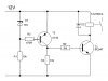
Here's a circuit that uses a low cost TL431 adjustable zener as a comparator to accurately set the trigger voltage.
The circuit switches when the Ref voltage, as determined by R2 and R3, equals 2.5V.
You can make the trigger point adjustable by replacing R2 and R3 with a 10k ohm pot.
When the input to the TL431 is below 2.5 volts the output is almost Vb.
When the input to the TL431 is above 2.5 volts the output is in the 2 to 2.5 volt range.
So the Q1 circuit needs to know the difference between Vb and 2.5V. Q1 turns on at 0.6 to 0.7 volts. If the Zener is 3.3V then Q1 will turn on/off at about 4 volts. You could turn D2 & R7 into two resistors, voltage divider and get similar results.
An interesting side note is that those two values of resistors (10.2k and 3.4k) are the only combination of 1% resistors that give an exact 3:1 ratio.
Other values can give close to a 3:1 ratio but not exactly.
An interesting side note is that those two values of resistors (10.2k and 3.4k) are the only combination of 1% resistors that give an exact 3:1 ratio.
Other values can give close to a 3:1 ratio but not exactly.
What is disturbing about the circuit that the OP attached, is that it is a well drawn schematic, meaning that this non-functional circuit is published somewhere!
And people will start copying it.
Wondering how come it does not work.
What is disturbing about the circuit that the OP attached, is that it is a well drawn schematic, meaning that this non-functional circuit is published somewhere!
And people will start copying it.
Wondering how come it does not work.
Fairly obviously as transistors require 0.7V to turn ON, and the 10V zener is between base and emitter, it will always have plenty more than 0.7V drive to the base holding it permanently ON. Even when the power is high enough for the zener to conduct, it will only limit the drive voltage to 10V, not remove it.
Obviously however drew the circuit hadn't the slightest idea how zeners work.
Try connecting a 100kΩ to 1 megΩ resistor between the base of Q1 and the collector of Q1 to add some positive feedback hysteresis.
Adjust the value until you get the desired response.
This site uses cookies to help personalise content, tailor your experience and to keep you logged in if you register.
By continuing to use this site, you are consenting to our use of cookies.