Continue to Site

Welcome to our site!

Electro Tech is an online community (with over 170,000 members) who enjoy talking about and building electronic circuits, projects and gadgets. To participate you need to register. Registration is free. Click here to register now.

  • Welcome to our site! Electro Tech is an online community (with over 170,000 members) who enjoy talking about and building electronic circuits, projects and gadgets. To participate you need to register. Registration is free. Click here to register now.

SIMPLE OPAMP CIRCUIT. PLS HELP!!

Status
Not open for further replies.

cyprio7

New Member
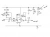
hi guys, i have been given a very simple opamp circuit to build, i have built it and it works perfectly. all it does is amplify a signal, and the variable resistor VR1 with value 1 mega ohm acts as volume control.

i have to write a report on this circuit, i know how the opamp itself works, but im a bit unsure on what the capacitors are for and a couple of the resistors.

could anyone please explain to me what the function of C1, C2, C3, C4, C5, R3 R4 are. i think its something to do with filtering of DC or hum from mains or something but not sure.

im new at electronics an this is my first ever project. any help is very much appreciated

thanks
 

Attachments

  • opamp_circuit.jpg
    opamp_circuit.jpg
    21.8 KB · Views: 472
C1: AC coupler capacitor, or DC blocking capacitor, so only AC signals will be amplified
C2: as above but it blocks any DC offset from the amplifier

Seems this amp is designed for AC signals?

C3: is a AC-decoupler to ground for any noise across R4 that provides a reference voltage to the +ve pin of the OPAMP
C4 & C5 are power-rail decoupling capacitors/smoothing caps, ie to ensure the +9V have as little noise on as possible
R3 & R4 set up a voltage divider to provide a (almost)_ constant reference voltage to the +ve pin of the opamp.

This OPAMP seems to be designed as an AC amplifier but eqaully set up as a DIFF-AMP.

Basically since it is an AC-coupler amplifier you can get rid of R3,R4,C3 and just ground the +ve pin.

All R3,R4,C3 will do is force the OPAMP to output an amplified version of the input AC voltage but sitting on a DC voltage, but that DC voltage is blocked by C2 meaning that R3,R4 and C3 are not really needed
 
Styx said:
All R3,R4,C3 will do is force the OPAMP to output an amplified version of the input AC voltage but sitting on a DC voltage, but that DC voltage is blocked by C2 meaning that R3,R4 and C3 are not really needed

R3 and R4 are requred to set a reference point for the amplifier. The reference is half the supply voltage (because R3 = R4), so the output is at half the supply voltage, so allowing the maximum output voltage swing before the output reaches the suppy rails resulting in clipping of the amplifier output waveform.

JimB
 
ah yes true, just noticed it was a single supply arrangement
 
Status
Not open for further replies.

Latest threads

Back
Top