Continue to Site

Welcome to our site!

Electro Tech is an online community (with over 170,000 members) who enjoy talking about and building electronic circuits, projects and gadgets. To participate you need to register. Registration is free. Click here to register now.

  • Welcome to our site! Electro Tech is an online community (with over 170,000 members) who enjoy talking about and building electronic circuits, projects and gadgets. To participate you need to register. Registration is free. Click here to register now.

Simple micro controller circuit and software needed

Status
Not open for further replies.
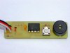
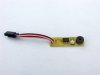
Here is the final prototype. It has a resistor on the input for overvoltage protection and space for up to 3 diodes to lower the supply voltage.

The prototype has one diode and a jumper in place of the other two diodes.

Mike
 

Attachments

  • FinalPrototype1.jpg
    FinalPrototype1.jpg
    33.9 KB · Views: 195
  • FinalPrototype2.jpg
    FinalPrototype2.jpg
    22.4 KB · Views: 174
Use software PWM. If instead of grounding one pin and turning the other one on and off to get the piezo to sound you swap both legs at the same time it'll double the effective voltage the piezo sees. It should increase the volume. Nigel explained that one to me a while back. It's like using a two way speaker instead of a single ended one.

The volume is pretty load as it is, and it is a lot easier to use the hardware PWM, but I may give this a try. Presumably doing it this way would get rid of the need for the 1K discharging resistor across the piezo.

In the meantime, I'm going to send off the prototype to Mrclox.

Mike
 
The volume is pretty load as it is, and it is a lot easier to use the hardware PWM, but I may give this a try. Presumably doing it this way would get rid of the need for the 1K discharging resistor across the piezo.

Feeding it in such a bridged way makes it a LOT louder, four times the power.

It's easy to do, requires no extra hardware (and as you say, one less resistor), and well worth doing.
 
I built a new board with the piezo sounder connected to two PIC outputs and drove the two pins in opposite directions. I was surprised when the volume was actually lower in this configuration.

In the end I built three test configurations (labelled A, B and C in the diagram - other parts left off for clarity)

Driving the piezo speaker single ended with no discharge resistor (as in circuit A) gave quite low volume.

Driving the piezo speaker double ended (as in circuit C) was much louder.

Driving the piezo speaker single ended with the 1K discharge resistor (as in circuit B) was louder yet.

Mike
 

Attachments

  • schems.png
    schems.png
    5.5 KB · Views: 239
hmm, that doesn't make sense =\
 
hmm, that doesn't make sense =\

No, it doesn't. It turns out that my software PWM routine was at a different frequency than the hardware PWM. The device is quite frequency sensitive.

When I made sure they were operating at the same frequency, then the double ended method is noticably louder, although I wouldn't say it was significantly louder.

I wrote a program that drives the piezo speaker both ways, alternating every few seconds so that I could hear them juxtaposed.

Mike
 
The more I fiddle with this and zero in on the resonant frequency, the larger the difference in volume between the double ended approach and the single ended approach becomes.

Mike
 
You should sweep your PWM's frequency while listening to it to find out the resonance of the piezo. They're incredibly loud at resonance. You can use a variable that gradually increases in your delay loop
 
Last edited:
Status
Not open for further replies.

New Articles From Microcontroller Tips

Back
Top