Continue to Site

Welcome to our site!

Electro Tech is an online community (with over 170,000 members) who enjoy talking about and building electronic circuits, projects and gadgets. To participate you need to register. Registration is free. Click here to register now.

  • Welcome to our site! Electro Tech is an online community (with over 170,000 members) who enjoy talking about and building electronic circuits, projects and gadgets. To participate you need to register. Registration is free. Click here to register now.

Simple(?) low current & voltage continuity tester

Status
Not open for further replies.

Lil_Guppy

New Member
I was just basically after a simple (if possible) continuity tester that only requires a small current and voltage to flow through the object in question (in this case, Estes model rocketry ignitors). All that it needs to do is light up a LED when the circuit is complete. Power supply will be from the main circuit, which uses 4xAA 2000mAH NiMH batteries.

I would rather stay clear of using an LED with a resistor to limit the current through the test circuit.

Thanks in advance.

Edit: I should have said that by "simple" I mean a circuit that is the bare minimum to suit the use. I don't really need all of the bells-and-whistles that a few of the circuits I have found have. As long as its relatively small, and is able to indicate continuity using a low current.

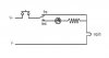
Edit 2: Now with crappy sketch goodness:
**broken link removed**

This is just a rough sketch, as I do not have the design software on this computer at the moment.
 
Last edited:
I think you'd need to determine the amount of current that would give you an indication without firing the motor - then plan to stay well below that.
 
That is indeed the plan. Whilst at this point in time I am using Estes brand ignitors, in the future I may use another brand, which may or may not have a similar firing current. I have read and heard that other brands have a safe test current of 50mA or less. So, I suppose it would be wise (for future-proofing) to use a continuity circuit that can test with less than 50mA of current.
 
10 ma is sufficient to power a LED.

In the portion of the circuit that contains SW3, LED2 and R2 you also have a connection that is essentially across LED2 and R2 - so no current will flow thru LED2/R2. If you were to put a switch there and size LED2/R2 for 10 ma you'd be all set. Not sure if that's what you want.
 
LED2 and R2 are intended to indicate that the fire button is closed and current is flowing. LED2 should only really stay lit if there is a problem with the ignitor (e.g. a short). It should actually be removed because as it is, it will not function (don't ask me what I was thinking there), and the continuity circuit will eliminate that need anyway. If there is a problem with the ignitor, such as a short, it will be apparent when continuity checks OK (SW2 in "S" position, SW4 closed), but the ignitor doesn't fire when SW2 is in position "A" and SW3 is closed.

Then again, if I did just use LED2 and R2 (with the appropriate value), I could move it in between SW2's "S" position and the top of SW3, getting rid of SW4 and CONT. TEST altogether...

Obviously I forgot to try to KISS :p

Edit: The latter is probably the best way to go I think. If I used say a 155Ω resistor (trimpot for adjusting between alkaline or NiMH) for R2, LED2 should draw 20mA with 4x1.2V NiMH batteries correct?
 
Last edited:
I believe this is the circuit. I would use 340 ohms for 10mA and you don't need a trimpot. 10 mA is plenty to see the LED is lighted.
 

Attachments

  • test ckt.jpg
    test ckt.jpg
    9.6 KB · Views: 394
A related question to this circuit:

SW2 is to be a key switch. The key switch I have found is stated as:
DPST Change Over Keyswitch

This keyswitch uses tubular keys with yellow plastic inserts to easily identify them. It has 2 positions and the key is removeable from both. There are 4 connection terminals, and it is a change over type - i.e. connection DPST.Contact rating is 2A, 250VAC.
Now, I am only an amateur when it comes to electronics, but to me a DPST switch is one that in one position, both circuits are on, and in the other position, both are off. But the description states "change over type", which to me means that in one position (in this case "S") the "safe" portion of the circuit is active, and the "arm" portion is not, and in the second position (i.e. "A"), the "arm" portion is active, and the "safe" is not.

I have sent an email to the supplier requesting clarification regarding this, but I was interested to know what other peoples opinions were. Is a change over type keyswitch a DPST switch in the sense that in one position, pins 1 and 2 are closed, and 3 and 4 are open, and in the other, 1 and 2 are open and 3 and 4 are closed?
 
hi,

A DPST switch is a Double Pole, Single Throw.

There are two isolated switches in the switch body.[Double Pole]

The switch operating lever/toggle will either Close or Open both switches, that is Single Throw.

This explains a number of switches:
https://en.wikipedia.org/wiki/Switch
 
Last edited:
Thanks for the reply. I do know how a DPST switch works, I am just wondering if they have gotten mixed up, or if it is me.

To me, a "change over" means that you can change over from one portion of the circuit to another with a single switch (a SPDT, which would have 3 terminals, or a switch with 4 terminals which in one position, two of the terminals are closed, and the other two are open, and in the other position, the closed/open states are switched, or changed over)

DPST kind of implies, as you stated, that either both sections of the circuit are active, or both are not, with no possibility of "changing over" from one to the other.
 
hi,
If you want to change over 'circuits'
You need a DPCO or DPDT, you can also get the type with a 'Centre Off' postion.

Did you look at the switch diagrams on the link?
 
Last edited:
Yes, I did look at the switch diagrams. What I am after would be a DPDT, but, the supplier where I found the switch described it as posted in the quote in one of my posts above. A change over switch could not really be a DPST switch, as they have described it...
 
Hi,

From their description, it sounds like one these, especially as its a rotatary type.
 
Last edited:
That makes sense. The way I visualised it (as a change over switch) was this:

**broken link removed**

Anyway, I might give them a call in the morning and see what they say (their email accounts are bouncing atm). Just interesting to see how others interpreted the description. At the end of the day, as long as it is a change over, and not an "all on" or "all off" DPST, then it will suit my purpose.

Edit: Should have known they wouldn't know....
 
Last edited:
Another simple (ha!) idea that I wouldn't mind adding to the whole project would be a battery status indicator. It only needs to give a go/no-go indication (e.g. green LED for battery OK and a red for battery LOW). It would be good to be adjustable, say with a jumper to select the appropriate components for a given voltage, to cater for different voltages (more than likely no more than a 9V battery). I have found a few via Google that operate on 6V, but none have really leapt out at me for use with a 4.8V battery pack (i.e. 4 x AA NiMH) which are also scalable up to 9V. Any suggestions, ideas or links that may be of help?
 
Status
Not open for further replies.

New Articles From Microcontroller Tips

Back
Top