billybob
Active Member
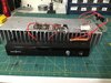
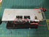
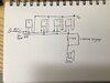
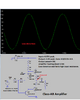
I have built a class A mono amplifier hopefully for a sub. With four C5200 transistors in parallel here is a picture of my setup and schematic...
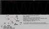
The output seems a little distorted at high volume, and it really doesn’t get very loud. How can I fix this? I am still trying to learn how audio amps work and the inductor and 4 ohm resistor is throwing me off. Right now I am not impressed with this amp.
The output seems a little distorted at high volume, and it really doesn’t get very loud. How can I fix this? I am still trying to learn how audio amps work and the inductor and 4 ohm resistor is throwing me off. Right now I am not impressed with this amp.