Continue to Site

Welcome to our site!

Electro Tech is an online community (with over 170,000 members) who enjoy talking about and building electronic circuits, projects and gadgets. To participate you need to register. Registration is free. Click here to register now.

  • Welcome to our site! Electro Tech is an online community (with over 170,000 members) who enjoy talking about and building electronic circuits, projects and gadgets. To participate you need to register. Registration is free. Click here to register now.

Simple Audio Amplifier

Status
Not open for further replies.
Thank you for your feedback

Mosfets have a very wide range of drain to source resistances. Unless you measure yours they might be well-matched or be either way mis-matched. The negative feedback should take care of the difference.

You will not be able to buy a "matched pair' of complementary Mosfets. Amplifier manufacturers buy thousands and match them themselves.
Usually the circuit adjusts the bias and feedback on the Mosfets to match them.

Your second circuit with the feedback connected properly to the Mosfets has the Mosfets idling at a very high current that might overheat them.

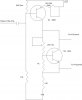
At +/- 30V the current idles at 1.0Amp. Even when I blast the speaker, the current from the power supply does not exceed 1.3Amperes. The Mosfets produce a lot of heat. I attached them to separate P3 CPU heat sinks with fan so that keeps them at ambient temperature level.

I will try the negative feedback with C1 removed as you have suggested.
 
Last edited:
Wow that's inefficient.

I looks like you've got it biased in class A which has low crossover distortion but it runs very hot.
 
Looks like you found the "other" lead :) Removing the cap shoudn't be a problem, becuase you're FET's are both turned off at the crossover point, but just leave it if it makes you feel better LOL! Glad you have it working well, after all your ears are probably pretty good distortion meters Heh!
 
Hmmm.. I haden't read all the way through the thread when I said your FET's are off during crossover. I wonder why that is? Seems they should not be conducting at idle
 
Last edited:
When the supply was plus and minus 12V both Mosfets were turned off at idle (class-B) which causes horrible crossover distortion.
When the supply was increased to plus and minus 30V then both Mosfets conduct 1.3A at idle (class-A) which causes them each to heat with (30V x 1.3A)= 39W.

A class-AB amplifier has both of its output transistors conducting a little at idle for very low distortion and low heat. The idle current is adjusted then is temperature controlled by a diode or a transistor.

An oscilloscope can show 5% distortion. Some people can hear 0.1% distortion. Good amplifiers have only 0.001% distortion.
 
I must not have been paying enough attention to know the Vcc changed...

I would try to replace the two 1.2K resistors with a Vbe multiplier with variable adjustment, and adjust to a good compromise between sound quality and quiesecenent current. I've build amps with very good results using this method. If you can't find a schematic, I'll try to scrawl you out for you. When you try it out, turn the bias all the way down, then while monitoring the current, slowly turn it up until the sound quality is good.

A 'good' amplifier is one that sounds good, especially when we're talking about a kitchen amp. No point in worrying about distortion you can't hear.
 
Last edited:
An amplifier with very low distortion is easy to make. It is difficult for an experienced person to make a distorted amplifier today.
A low distortion amplifier produces wonderful sounding music.
A distorted amplifier sounds like a cheap toy.
 
I've gotten more than satisfactory results with the methods I've described, usually as good or better than most of the commecially availble units, according to my ear and my friends ears. For this design, it's not a perfect solution, but most likely an improvment nevertheless.
 
I must not have been paying enough attention to know the Vcc changed...

I would try to replace the two 1.2K resistors with a Vbe multiplier with variable adjustment, and adjust to a good compromise between sound quality and quiesecenent current. I've build amps with very good results using this method. If you can't find a schematic, I'll try to scrawl you out for you. When you try it out, turn the bias all the way down, then while monitoring the current, slowly turn it up until the sound quality is good.

A 'good' amplifier is one that sounds good, especially when we're talking about a kitchen amp. No point in worrying about distortion you can't hear.

I thought Vbe multipliers are commonly used in BJT push-pull amplifiers. Didn't even hit my thought of using that for a MOSFET amp. Thanks for suggesting that!

Please post schematic.
 
Last edited:
An amplifier with very low distortion is easy to make. It is difficult for an experienced person to make a distorted amplifier today.
A low distortion amplifier produces wonderful sounding music.
A distorted amplifier sounds like a cheap toy.

By distorted you mean the type of "pleasant" distortion usual encountered in Tube amplifiers ?
 
I don't want to sound mean about your amp but the FET gates are AC coupled to the power supply rails, so it is going to be very affected by power supply ripple etc.

I'm guessing that up to now you have been running the amp from a +/-30 volt REGULATED psu??
 
I thought Vbe multipliers are commonly used in BJT push-pull amplifiers. Didn't even hit my thought of using that for a MOSFET amp. Thanks for suggesting that!
Please post schematic

I haven't used one w/a FET amp before, but there is no reason it shouldn't work.

I'm trying to find a schematic that is as simple as possible. I'll post later.
 
I don't want to sound mean about your amp but the FET gates are AC coupled to the power supply rails, so it is going to be very affected by power supply ripple etc.

I'm guessing that up to now you have been running the amp from a +/-30 volt REGULATED psu??

Well what other kind of PSU is there ? Unregulated ? That doesn't sound like a PSU to me if its not regulated.
 
I haven't used one w/a FET amp before, but there is no reason it shouldn't work.

I'm trying to find a schematic that is as simple as possible. I'll post later.

Thanks, I appreciate your efforts!
 
Most PSU's for a audio amp like yours would simply use a transformer, rectifier, and a filter cap. But since you are still experimenting, you are using a regulated and well smoothed supply. So, if you were to build a stand alone amp, you'd need a different design to avoid hum.
 
"The people who cast the votes don't decide an election, the people who count the votes do."
-Joseph Stalin

Just ask Mr Ahmenidajad!
 
Here is a schmatic of a Vbe multiplier. This drawing is for illustrative purposes only!!! I have not prototyped and do not guarantee correct operation. I have not done a detailed analysis, but if you want to try it, I suggest you build it on a bread-board by itself, and try to set it up before incorporating it into your circuit. To set it up, turn VR1 to a maximum value, and VR2 to a minimum value. Connect two resistors, about 1k each, across the outputs labeled To N channel, To P channel. Set VR1 for 0V at the junction of the two 1k Resistors. Then set VR2 for ~4V across the resistors. If that works, you can add it to your amp, but turn VR2 back down, and then back up slowly in your circuit.

The component values for this circuit are calculated, and not necessarily 'standard' values. Use values as close as possible. This circuit is experimental, and won't give the best results, but will hopefully demonstrate the principles involved. It may requre additional emitter follower or source follower devices to be placed before the output drivers. Sorry, I do not have a chance to prototype this circuit. You'll just have to play around with it. Getting the driver to correctly output the signal efficently required complexity. It would be a good idea to simulate the ckt if possible.

If you choose not to use this, you may just lower the value of your 1.2k Ohm resistors in your original circuit.
 

Attachments

  • vbeMult.jpg
    vbeMult.jpg
    34.8 KB · Views: 160
Oh one more thing, the transistors will only tolerate Vbe=40V. I Think you're up to about 80V total rail-2-rail now. Use Hi-Voltage devices.
 
Last edited:
If you choose not to use this, you may just lower the value of your 1.2k Ohm resistors in your original circuit.

Thank you very much for all your efforts on this!

Hopefully, I will have enough time this week to test all of this in the lab.
 
Status
Not open for further replies.

New Articles From Microcontroller Tips

Back
Top