Continue to Site

Welcome to our site!

Electro Tech is an online community (with over 170,000 members) who enjoy talking about and building electronic circuits, projects and gadgets. To participate you need to register. Registration is free. Click here to register now.

  • Welcome to our site! Electro Tech is an online community (with over 170,000 members) who enjoy talking about and building electronic circuits, projects and gadgets. To participate you need to register. Registration is free. Click here to register now.

Signal Input to your Logic Circuits

Status
Not open for further replies.

Suraj143

Active Member
Whats the best method to give inputs to your logic circuits from long distance inputs like something over 30m length!! By use a transistor or opto or any other method??

Ex: I need to read a reed switch from a 5V logic circuit.The reed is place at 30m length.
What to use in the input circuit a transistor, opto etc....?
 
The most important question to ask is how long after the reed switch closes are you willing to wait before the logic signal changes state? IOW, it is all about how much filtering you are able to do where the 30m wire connects to your logic board?
 
Five volts will travel very well at a distance of 30 meters!!! Just connect the wires and it will work!!!
 
It depends on the frequency.

If you use the appropriate driver and make sure the cable is terminated with its characteristic impedance a high frequency signal can travel a long way.
 
The most important question to ask is how long after the reed switch closes are you willing to wait before the logic signal changes state? IOW, it is all about how much filtering you are able to do where the 30m wire connects to your logic board?

The delay doesn't matter max 1 Second is fair enough.

The ex i stated a reed.But it can be a dry contacts on a relay or a push button etc.....which is placed in over 30m length.
 
The cable would have the be 300,00km long for the delay to be a second.

It it's a low frequency signal (10Hz or so) it doesn't matter, if you're worried about noise a 100nF capacitor at the signal input will get rid of it.
 
The cable would have the be 300,00km long for the delay to be a second.

It it's a low frequency signal (10Hz or so) it doesn't matter, if you're worried about noise a 100nF capacitor at the signal input will get rid of it.

So you all telling just connect the wires to the logic circuit & place a 0.1uF capacitor??
 
This will work only if it's a really low frequency signal.
 

Attachments

  • Digital signal 30&.PNG
    Digital signal 30&.PNG
    710 bytes · Views: 179
Hero thanks but that is too much parts.Also in the input switch area there doesn't have power.What I mean was place all the circuits in one place & extend only the two signal wires.
 
Yep, that's the answer!! Reed switches can't physically operate at high frequencies. Just connect the wire!! If you're picking up noise signals that interfere, add a capacitor!!
 
Hero thanks but that is too much parts.Also in the input switch area there doesn't have power.What I mean was place all the circuits in one place & extend only the two signal wires.

It's only two extra parts: a resistor and a capacitor.

If there's no room in the switch then move them to the board with the IC on.

If you only have two wires then use a pull down and run 0V to the switch or keep it how it is and run 5V and the input instead.
 
Ok, the problem is that the 30m twisted pair is a huge "antenna" for all kinds of bad stuff: EMI, Lightning, 60Hz, Static that you do not want it to conduct into your logic board. For this reason, I suggest not connecting either wire of the twisted pair directly to GND or VCC. Here is how I would do it:
 

Attachments

  • Twisted.png
    Twisted.png
    45.5 KB · Views: 197
The cable would have the be 300,00km long for the delay to be a second.

It it's a low frequency signal (10Hz or so) it doesn't matter, if you're worried about noise a 100nF capacitor at the signal input will get rid of it.

hi hero,
I think you have a typo.
Propagation velocity is 300 000 000 m/s 300,000 kms/sec

In a conductor its a 'little' slower

In fact the twin cable would have to be only 150,000k long..
 
Last edited:
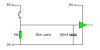
1) The simplest way I can think of to answer this is, if you want to put all the circuits in one place and extend only the two signal wires, you have to put the circuits all in one place with your hands, then extend the signal wire with your hands. I seem to be missing some information about why it is difficult to, put the parts on the circuit board, connect the wires there, and extend the wires to the switch.
2) Why is it important that there doesn't have power at the input switch area?
3 Why do you think the "best method to give inputs to your logic circuits" only requires one part?
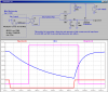
4) The fact that a reed switch is being used limits the frequency to less than 1000 cycles per second.
5) The "not connecting" method requires even more parts than the resistor and capacitor method.
6) I'm happy that you got over the need to !!! every sentence. Thank you.

When a circuit is this difficult, I expect I will learn something from the experience of working on it. I eagerly await your information.
 
Hi sorry for the inconvenience.

When I see Hero99's circuit I thought the whole circuit is the input signal circuit.But after checking out that circuit I saw there is only two parts.That is a resister & a capacitor.That's what I'm going to use.

Thanks for that.

The problem is why that resister should place near the switch?Why not place that near the logic circuit?
 
Last edited:
The problem is why that resister should place near the switch?Why not place that near the logic circuit?

I've already suggested putting the switch near the logic input, see my previous post.

That has the advantage of only needing a two wire piece of cable.
 
Hi sorry for the inconvenience.

When I see Hero99's circuit I thought the whole circuit is the input signal circuit.But after checking out that circuit I saw there is only two parts.That is a resister & a capacitor.That's what I'm going to use.

Thanks for that.

The problem is why that resister should place near the switch?Why not place that near the logic circuit?

hi Suraj,
If you use that basic circuit over a 30mtr length of cable its going to be subject to all types of electrical interference.
If you want a trouble free circuit use the method that Mike has posted.
 
You can reduce the "interference" (if there is any) by reducing the resistor value to as low as 470 ohms, and the capacitor can be increased to hundreds of micorfarads without hurting the chip or the operation of the circuit. If you actually have interference problems after that, you can build the "guaranteed to survive lightning strikes" circuit.

C'mon guys. This is basic light bulbs and batteries, not mil spec hospital equipment.
 
Status
Not open for further replies.

Latest threads

New Articles From Microcontroller Tips

Back
Top