Continue to Site

Welcome to our site!

Electro Tech is an online community (with over 170,000 members) who enjoy talking about and building electronic circuits, projects and gadgets. To participate you need to register. Registration is free. Click here to register now.

  • Welcome to our site! Electro Tech is an online community (with over 170,000 members) who enjoy talking about and building electronic circuits, projects and gadgets. To participate you need to register. Registration is free. Click here to register now.

signal conditioning

Status
Not open for further replies.

qtommer

Member
Bear with me on this, it's a long post but I believe a very simple question for the pros in this forum..=)

im reading values from a SHARP GP2Y0A21YK Distance Sensor and inputting the sensor output values to a 877A for ADC conversion.

I have pretty much implemented the ADC and output the digitized values to an array of 8 LEDs representing the MSB to the LSB of the result.

However, due to the imperfection of output voltage values from sensors, the digitized ADC result on the LEDs tend to flicker at certain bits while there are dominant bits which clearly stay lit. (thus indicating a somewhat vague result with superimposed noise)

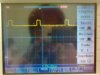
I scoped the sensor output on an oscilloscope and found out that the Vavg is stable but there is noise superimposed on it at about 300mV on average...Hence, I inserted a smoothing capacitor on the signal lines and indeed the digitized result became more stable with less LED flickering. However, I would really love to get a stable voltage with no flickering of the LED's whatsoever.

Hence, there are 2 methods i propose to undertake to increase the stability of the digitized results and would really love advice on it...

1) Reducing the resolution of the ADC
Im currently doing a 10 bit resolution ADC.If i further decrease the resolution, the smaller noise signals will then not affect the ADC process.
Is there any way I can reduce the resolution to 8 bits? The 877A uses a 10 bit resolution into 2 registers ADRESH and ADRESL. Is resolution decreasing possible?

2) Adding another stage of signal conditioning after the capacitor.
Any suggestions on a good signal conditioning circuit for the aforementioned purpose?

Out of the 2 which would be more advisable?


Thank YoU!=)
 
You can use the ADC in "left-justified" mode (ADCON1.ADFM=0), then ADRESH will give you an 8-bit result.

A simple filter at the input is probably ok, remember that heavy capacitance directly at the ADC's input may affect the measurement; but most important is the source resistance (see section 11.1 of datasheet).

What you have is probably calling for filtering on the PIC itself (or like the previous poster mentioned, digital filtering). A simple average of eight or sixteen readings may be a good initial step. For example: take eight readings, average them, and then update the LEDs with this averaged value.
 
thank you for the suggestions

i have tried the left mode justification but the flickering still is there..

i will try out the digital filtering when i get access to lab facility tomorrow=) brilliant idea btw..=)

btw i have a question on the source resistance affecting the conversion time of the ADC. has this anything to do with signal power transfer or is it just purely affecting the time conversion... Is it due to the RC time constant ? basically what is the engineering principle governing this occurence? thanks=)
 
Filter do just help half ways. If the signal is just around two values the digits will keep toggling even with a filter. It will be better but will not disappear. You should have a filter but the simple analogue you use it just fine and much better than only a digital filter. Do not try do read a high frequency signal (noise can be that even if your signal is not) and only filter it digitally. There is a risk that the digital noise will be synchronized with the sample rate and this will result in a value totally wrong. Trust me, this can be very frustrating and very difficult to track down.

To get rid of the toggling completely the trick is to add hysteresis! After toggling to one digit, require that the signal goes back a little before changing back. You do not need this to be several digits values, just parts of one digit.

PS. I am new to this forum but I am not new to electronics. Glad to join here as well.
 
Maybe a little more info? 300 mv seems like quite a lot. What is the frequency of the noise?
What speed do you require? ie: 1 reading a second or 1 every .1 sec.?? How many bits do you see toggle now?
 
Maybe a little more info? 300 mv seems like quite a lot. What is the frequency of the noise?
What speed do you require? ie: 1 reading a second or 1 every .1 sec.?? How many bits do you see toggle now?
basically my application uses the analog sensor for distance sensing for a self parking car. Hence, I am constantly updating my PIC at 9ns intervals with distance values till I reach certain several "trigger distances" which will call up corresponding routines to be done.
my scope in the lab does not seem to be able to pick up the frequency so im guessing that the noise frequency is very low. (this happens on the scope when the frequency is <20Hz) an average of 3-4 bits are toggling. thanks=)


To get rid of the toggling completely the trick is to add hysteresis! After toggling to one digit, require that the signal goes back a little before changing back. You do not need this to be several digits values, just parts of one digit.

sounds intriguing.. how do i accomplish hysteresis? is it an internal software thing or an external hardware? thanks=)
 
I am constantly updating my PIC at 9ns intervals
Do you mean you are attempting to acquire ADC readings at this rate (9nsec - hope this is a typo and you mean 9msec)? If this is the case read section 11 of the datasheet carefully (s11.1 and s11.2 in particular), the absolute minimum ADC sample rate is 1.6usec.

an average of 3-4 bits are toggling
This is must be pretty good noise, yet you can't quite resolve it with the scope. You may have some grounding issues; but first I would be more concerned about not complying with the acquisition time requirements of the ADC.

If you think you are compliant with the acquisition time, then more description on your circuit is probably worth while. How is the sensor connected? What is the connection between the sensor and the PIC? What do the supplies to both look like (filtering, etc)?
 
Hysteresis is used in all kinds of situations. It can be made in hardware or in software, in this case it must be done is software. The principle is the if you are passing a level say from negative to positive, you add a small value so that the signal must drop a little bit more before it can go below the level again. Same for the reverse.

The awesome with hysteresis is that you can have a really fast response in the same time as the display will be stable. With filtering, you can have a stable display only with the trade off of a very slow response.

In your situation you do not have only one level but several, one per the the resolution of the digits. But it doesn't matter, just keep track of the digits instead of values of the actual signal.

What you must do is something like this:

If the signal is passing to a new value, set a flag that forbid setting the previous digit back again. Either you just define a minimum time or you can set it infinitive resulting in that the value must dropp two values below. Both will work but the second will mean that the display will skip one number if going up and down again. I hope you understand the principle?
 
btw attached is the scoped output signal from the sensor. upon measurement today, there seems to be a square wave at occasional intervals. Datasheet does not indicate that this occurs =/...is this expected or is there a problem with the sensor..? the amplitude of the square wave is approx 300mV..
 

Attachments

  • 22112010027.jpg
    22112010027.jpg
    1.1 MB · Views: 171
Last edited:
Looks strange. If the analogue output should just correspond to the distance it shouldn't be there. I checked the data sheet and I think you should see a continuous signal. Check if this square wave exists in the power to the sensor as well. Have you any high current flowing in the system?
 
Those pulses are spaced 4 divisions apart. What is the time/div, 25us?

I briefly looked at the GP2Y0A21YK and there is some indication that it takes large pulses of power, and is recommended to have a nice hefty capacitor near it.
 
Looks strange. If the analogue output should just correspond to the distance it shouldn't be there. I checked the data sheet and I think you should see a continuous signal. Check if this square wave exists in the power to the sensor as well. Have you any high current flowing in the system?
you were right! the power supply was indeed the culprit. everything is working fine now..THANKS=)


I briefly looked at the GP2Y0A21YK and there is some indication that it takes large pulses of power, and is recommended to have a nice hefty capacitor near it.
I did just that and the signal stability improved. THANKS=)
 
Status
Not open for further replies.

Latest threads

New Articles From Microcontroller Tips

Back
Top