David Banner
New Member
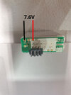
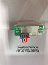
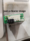
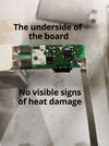
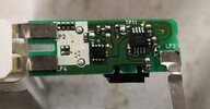
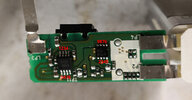
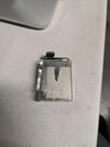
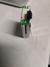
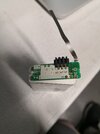
I shorted the + - external connections on the battery for less than half a second. Now the battery is not charging, it is not being recognised in the charger. The camera doesn't see it either. I've opened the battery pack and there are no obvious signs of damage. I am getting reading of DC 7.6v on parts of the pcb (which is correct), but the external terminals are reading 0.151v. I've attached images that I've put some info on. I can do basic multimeter reading where I connect a to b and provide info on the readout.