Continue to Site

Welcome to our site!

Electro Tech is an online community (with over 170,000 members) who enjoy talking about and building electronic circuits, projects and gadgets. To participate you need to register. Registration is free. Click here to register now.

  • Welcome to our site! Electro Tech is an online community (with over 170,000 members) who enjoy talking about and building electronic circuits, projects and gadgets. To participate you need to register. Registration is free. Click here to register now.

"Shift1 System" drives LCD from 1 PIC pin

Status
Not open for further replies.

Mr RB

Well-Known Member
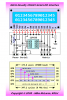
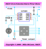
Here's something I have been working on recently. It's a simple system using 2 timed RC networks and a latched shift register (74HC595) to give 7 latched digital outputs from timed pulses sent by 1 PIC pin. The concept is open source as are the schematics.

I have supplemented that with full Mikro C source code (again open source), so it's as easy to use as any bit banged serial library. The beauty is that only one cheap logic chip and 2 resistors and 2 caps are needed to drive a text LCD from a single PIC pin. So it can pretty much turn any LCD into a "serial" LCD.

**broken link removed**

**broken link removed**

**broken link removed**

Here is the prototype running a 16x2 LCD from 1 PIC pin;

**broken link removed**

The full system with schematics etc can be seen here;
Shift1 System for 1-wire Shift Registers


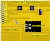
I have also designed a neat little PCB that contains the Shift1 system and also has room for a PIC 12F675, so it can be used for many control and display applications (it just plugs on the back of an LCD);

**broken link removed**

Also check at the bottom of that page, there is a link to a page with 4 open-source projects I've just released using the PIC 12F675 and Shift1-LCD system;

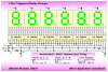
* Clock 12:00:00 (can be adapted for timers)
* RC Servo tester controlled by pot, displays actual pulse uS
* Solar charge controller, shows battery volts, controls charging
* Tacho shows lathe or drill RPM and an averaged RPM
 
NICE!!!!!!!!! dude this is cool. I am going to print this out heh
So basically the cap charging time stops the pulse from hitting something else correct? heh i dont know but it seems complex and very cool. Great job
 
Great! This is, perhaps, the best serial LCD I've seen. Have to try this one out right away.
Thanks Roman!:)
 
Roman,

Would you mind a suggestion? You might consider bringing out four or five of the latch outputs on the board for use as keypad row or column drivers like I do with my novelty "Breadboard Buddy" 1-pin LCD interface.

k8lh-12f635-lcd-interface-png.35096

You can set those latch outputs any way you want and use them for driving a keypad as long as don't toggle the '595 output connected to the LCD 'E' pin. The additional functionality provides a lot more capability for those little 8-pin (or other) PIC projects.
ezlcd-project-example-png.35098

May I ask if you considered using different RC values for a shorter RC time constant? I ask because I thought that extra '595 output might be kind of handy to drive a small piezo speaker which is pretty much a standard item on all my projects but then I realized that the time required to send a byte to the '595 (approx. 600 to 800 usecs) to toggle the speaker would limit me to a tone no higher than about 800-Hz. Are shorter RC time constants more difficult to work with on this project?

Kind regards, Mike
 

Attachments

  • K8LH 12F635 LCD Interface.PNG
    K8LH 12F635 LCD Interface.PNG
    38.1 KB · Views: 3,701
  • EZLCD Project Example.PNG
    EZLCD Project Example.PNG
    24.3 KB · Views: 3,832
I hadn't seen that 2007 EDN article. I did know of some hobby people using an RC network on a shift register back in the old days (talking about the '90s) but there were some issues because of the lack of latching meaning it was only good for LED mutiplexing and some non-critical tasks and it was chip specific because not all of the manufacturers made logic chips that had reliable schmidt threshold voltages etc, some were prone to latchup or erratic operation.

Before I got too deep into this project I did some testing on new HC series CMOS and found the HC CMOS schmidt threshold voltages to be reliable and the inputs extremely resistant to latchup even with slow changing input voltages. Modern logic chips are so far advanced from the old things of 10 or 15 years ago! The HC series have great schmidt inputs.

So it's a combination of an old idea, plus some excellent modern shift registers and a bit of creating and experimenting thrown in... ;)

And thanks people for the nice words! :)

PS. I've added a temperature controller to the Shift1-LCD Projects page too.

(edit)I just saw your last post Mike. It's an interesting idea, I hadn't really imagined connecting a 4x4 keypad to the thing, the PCB was designed to be little and cheap for making little controllers and "smart displays" etc. But now you said it, a 4x4 keypad could be connected to the 4 LCD data pins (D4-D7) and to 4 inputs of the 12F675.

You can make the time constants shorter, but the values I chose were to make the shortest pulse 1uS, which is usable on 12F675 (or any PIC) on 4MHz osc speed. That was a deliberate design factor. The 1:20 ratio of the two different time constants were chosen for max reliability, I wanted large safety margins around the timed values that work so it would not be fussy to use.

I tested on the finished hardware and many of my time constants (shown in green on the picture above) can be shortened a lot especially the recovery times. But 3 to 4mS to send a character is acceptable, there's not much to be gained by reducing that to 2.5mS or even 2mS. Data reliability is important, I set one up sending characters and commands to the LCD with no breaks (about 320 per second) for a full day, about 10 million bytes sent with never a glitch. You know if you get a glitch on a command as chars will be in the wrong spot or it will corrupt the whole display etc.

As for the speaker etc, since the 12F765 only needs 1 pin to drive the LCD and backlight, there are 3 to 5 pins still availble for things like that.
 
Last edited:
Today I had a think about your question again Mike, you are right in that the spare pin (ie LCD backlight) can be driven quicker. I missed that in my hurried 4am post above. :)

To change the backlight bit, you only need to send 3 bits then the latch pulse;
E -> RS -> backlight -> Latch pulse.
E should be a 1 bit (so LCD is not affected), then RS can be a 1 to save time and then the bit to control the spare (backlight) pin. The latch pulse period and it's recovery period can be reduced quite a bit too based on my tests.

I think you could get the total time to change the "spare" bit down to 400uS or so.

That would make it usable for many other control tasks where I originally had just thought about using it for a backlight control. Thanks for that.
 
I like your method more and more each day. Simple, elegant, intuitive, absolutely brilliant!!! Lots of possibilities and much quicker overall load times if you don't have to worry about strobing one of the outputs.

Kind regards, Mike

rb-shift1-7-segment-png.35534
 

Attachments

  • RB Shift1 7-Segment.PNG
    RB Shift1 7-Segment.PNG
    34.6 KB · Views: 3,788
Last edited:
Very nice diagram Mike! And thanks for mentioning my name on the picture, I feel honoured. :)

Just remember that the last bit shifted in will have to be a 0 bit due to that being the latch pulse. I assume that's why you have the QA pin of U1 shown not connected. That's a nice setup, it's efficient because you can shift all 47 bits in nice and fast then just do one final latch pulse to latch all 6 IC outputs.
 
G'day Roman,

Been busy as hell here the last few weeks but tonight I finally got started on the addon board for the charge controller. I did the design in lochmaster and mate feel free the pic as you please.

shift-1-charge-conroller-board-jpg.35636


Fist Draft and I hope it's right... As the Nfet is a 40 amp one I left plenty of space for the source and drain pads to connect.

Cheers Bryan
 

Attachments

  • Shift-1 charge conroller board.JPG
    Shift-1 charge conroller board.JPG
    84.9 KB · Views: 2,211
Looks good Bryan! :) Just a couple of small additions;
1. GP3 needs a pullup resistor to +5v. The PIC does not have internal pullup on GP3. 4k7 or 10k will be fine.

2. Since this is for power control I would add a 4k7 resistor from FET gate to ground. The PIC will boot up with all pins high impedance (for a short time), and in cases like that, or in a fault latchup etc it's best to keep the FET off at all times unless the PIC is specifically turning it on. :)

3. I would add a fairly large cap on the ADC input, from GP0 to ground. Somewhere around 470uF or even 1000uF will be fine. The battery charge controller software has a built in 10 second ON period, which will do a lot to stop the load jittering on and off, but lots of smoothing on the ADC input is still good. You don't want it triggering on any little voltage transient like when appliances are turned on and off. That is also assuming a fairly large value for the trimpot, 10k would be a minimum, 50k is about optimal. The speed that the battery bank charges or discharges is VERY slow, so don't be afraid to use a quite severe filter here (ie 50k -> 1000uF).

4. Obviously your FET source is connected to battery ground and your load is from battery + to FET drain? I would fuse the bat + wire to the load that should protect both load, wiring and FET.

5. It's not a necessity but you might want to add some FET protection. If this is used to drive an inductive load like a pump etc you might want a snubber between the FET drain and source. Maybe a 47 ohm resistor and 0.33uF (in series)... I'm not great with snubber design and just guessing on your load but that's a starting point.
 
Hi Roman,
Thanks for the input tomorrow if I get time I'll do some changes to the board using your suggestions. Anyway what with work and the fact I might be moving back on the grid means I will be able to test the shift-1 lcd setups but soon they will go into storage as if this 5 acre farm in town goes ahead a big move will be in store. As usual it's always been xmas when I move places.

Cheers Bryan
 
I've only just twigged after reading this post that Mr RB = Roman Black lmao

I've followed a lot of your stuff since the early days of the Piclist Mr RB :)
 
Well for people too lazy to get the parts values off the schematic on this page;
Shift1 System for 1-wire Shift Registers
(just kidding Atom! ;))

Code:
Shift1-LCD Bill of Materials;
Any standard text LCD (Hitachi 44780 driver)
74HC595
2n2 (2.2nF) non polarised cap (x2)
1k5 (1.5k) resistor
33k resistor
header pin connectors.

(optional)
PIC + socket (generally 12F675 for my code examples)
8MHz xtal + 22pF caps (2x) (some projects don't need xtal)
(optional)
PFET to drive LCD backlight (any that are capable of 1 amp)
68 ohm resistor for LCD backlight (gives about 25mA, some backlights need more current so choose a lower ohms resistor)

The Shift1 projects on my web page here;
Shift1-LCD Projects
have all been tested so the PIC 12F675 code works.

It's very fast to get a smart LCD display or simple controller built on a Shift1 PCB, much of the benefit is in the little PCB which is very fast to assemble (thats why I made them). The effort to solder up a LCD project from scratch is a lot more by the time you are connecting wires and contrast pot, PIC pins etc, and then it is probably going to be bulkier etc and not fit neatly on the back a LCD.

If anyone wants to buy Shift1-PCB can contact James here;

he can arrange bulk prices if someone wants to order a few PCBs or more.
 
Amazing Roman, I had it set in my mind that 2 pin was the lowest you could go!
You and mike always have the best schematics, makes me feel like mine were drawn by 3 year old kids with markers:eek:
 
If speed is an issue, you can reduce the recovery times with a diode across each resistor.
 
Status
Not open for further replies.

Latest threads

New Articles From Microcontroller Tips

Back
Top