Manoj_maniyan
New Member
Hi guys,
Can anyone help with my question?
I am using Seven segment cathode display. I need to display 1., 2., 3., 4., etc. When i do coding like B00111111 | B10000000, this should display as 0. (zero+dot)
But I am not getting this result. I am getting only ‘.’ (dot)
I don’t know why dp is getting prioritization when I add to another digit.
digitalWrite(STCP_pin, LOW);
{
shiftOut(DS_pin, SHCP_pin, MSBFIRST, dec_digits[(buf & 0x0f)] | 0x80) // dp ‘on’
} else {
shiftOut(DS_pin, SHCP_pin, MSBFIRST, dec_digits[(buf & 0x0f)]); // no dp
}
digitalWrite(STCP_pin, HIGH);
Help me?
Redefining the question:
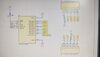
I think I have an issue with the shift register.
am using TPIC6C596 shift register and this register is capable of sending 8 bits. When I start sending 8 bits, I am getting only the last bit (i.e decimal point). But without the 8th bit (decimal point), my shift register can transfer whole 7 bits at a time. May i get the solution for this? When I implement in the proteus I am getting proper output. while doing the same in the hardware, I face the issue. For example, 0b00000110, I am getting the value as 1. if i do, 0b00000110 | 0b10000000, I am getting only .(dot) without 1. I should get 1.(one + dot). shiftOut(DS_pin, SHCP_pin, MSBFIRST, dec_digits[(buf - 0x30)]|0x80); What will be the issue.?
0r my doubt is when supply goes to decimal point, all the other pins goes to OFF condition.
When supply don’t go to the decimal point, all the other pins goes to ON condition.
Is that correct?
Can anyone help with my question?
I am using Seven segment cathode display. I need to display 1., 2., 3., 4., etc. When i do coding like B00111111 | B10000000, this should display as 0. (zero+dot)
But I am not getting this result. I am getting only ‘.’ (dot)
I don’t know why dp is getting prioritization when I add to another digit.
digitalWrite(STCP_pin, LOW);
{
shiftOut(DS_pin, SHCP_pin, MSBFIRST, dec_digits[(buf & 0x0f)] | 0x80) // dp ‘on’
} else {
shiftOut(DS_pin, SHCP_pin, MSBFIRST, dec_digits[(buf & 0x0f)]); // no dp
}
digitalWrite(STCP_pin, HIGH);
Help me?
Redefining the question:
I think I have an issue with the shift register.
am using TPIC6C596 shift register and this register is capable of sending 8 bits. When I start sending 8 bits, I am getting only the last bit (i.e decimal point). But without the 8th bit (decimal point), my shift register can transfer whole 7 bits at a time. May i get the solution for this? When I implement in the proteus I am getting proper output. while doing the same in the hardware, I face the issue. For example, 0b00000110, I am getting the value as 1. if i do, 0b00000110 | 0b10000000, I am getting only .(dot) without 1. I should get 1.(one + dot). shiftOut(DS_pin, SHCP_pin, MSBFIRST, dec_digits[(buf - 0x30)]|0x80); What will be the issue.?
0r my doubt is when supply goes to decimal point, all the other pins goes to OFF condition.
When supply don’t go to the decimal point, all the other pins goes to ON condition.
Is that correct?