Continue to Site

Welcome to our site!

Electro Tech is an online community (with over 170,000 members) who enjoy talking about and building electronic circuits, projects and gadgets. To participate you need to register. Registration is free. Click here to register now.

  • Welcome to our site! Electro Tech is an online community (with over 170,000 members) who enjoy talking about and building electronic circuits, projects and gadgets. To participate you need to register. Registration is free. Click here to register now.

Sequential Logic Help

Status
Not open for further replies.

PedroDaGr8

New Member
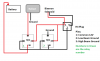
I got some great help on here before, I built the first of the solid state MOSFET switches and it WORKED whoo hoo. Though it subsequently died a quick death a la canine (thankfully it wasn't plugged in at that time)

Now I am back with another question. I am trying to figure out how to switch a signal based on a previous state. I guess I need to explain.

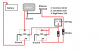
There are two signals S1 and S2. I want it so that S2 only passed only when S1 was on before S2 turned on, irrespective of S1's current state. THe problem that is complicating things is that sometimes S1 and S2 will turn on together. If this were not the case, I realized I could use an NOR RS Latch combined with an AND gate to accomplish this, but the fact that S1 and S2 could be on at the same makes this not work. Not sure how I can pull this off. Any ideas would be greatly appreciated.

Signal is a constant positive voltage (what ever voltage needed can be used).
 
You are describing a "state machine".

What resets it back to the starting state? Interruption of input power?
Do you want to use logic chips?
How about relay logic?
 
Likely interruption of input power will reset it. Not 100% on that yet as I was more worried about implementing this yet. I will use what ever I can get to work. Ideally, logic chips as they are cheaper and smaller but will use relays if necessary.

I have in the past come up with a circuit, using relays, that can take care of the situation where S1 and S2 are never present at the same time. Unfortunately, this other setup is driving me bonkers.
 
Last edited:
A relay circuit is shown first.

S1 and S2 are momentary contacts.
R1 and R2 are normally open relay contacts.
R1 and R2 are also the coils of said relays.

Press S1 first, then S2 second or Press S1 and S2 simultaneously and both relays latch. If you press S2 first and S1 second, nothing happens, except that S1 is latched, now the circuit is waiting for S2 to be pressed again.

Interrupting power resets the relays.

A dual D-flop version is shown below.

Begs the question of what happens if the rising edge of S2 is absolutely coincident with the rising edge of S1? As it is, depending on the logic family, S1 would have to preceed the rising edge of S2 by a few nsec.
 

Attachments

  • RelayS1S2.gif
    RelayS1S2.gif
    84.7 KB · Views: 381
  • S1S2.gif
    S1S2.gif
    87.7 KB · Views: 392
Last edited:
Hmmm, interesting. Is there any way to extend the required gap between s1 and s2? I guess to explain this better I should mention EXACTLY what it is going to be used for. It is an attempt to get around using a delay timer to knock-out the pass-to-flash feature in most cars. For people who are running HID's, flashing the HID's are bad for the ballast and REALLY bad for the bulb. While I have made a circuit that requires the low beam to be on first (for both positive and ground switched systems) in systems where either the low is on or the high is on. It fails to work on the systems where the lows come on with the highs when the high beams are flashed. This is working to get around that.

So basically I want:
If the inital state is the lights are off and the high beams are flashed nothing turns on. If the initial state is the low beams are on and the high beams are flashed the highs are activated.


I am worried that since these are analogue circuits (the cars headlight circuits) the time scale I am working on is likely milli to micro seconds. Either way, I am going to try and build this to see if it works. Unless you say nope won't work.:D

By the way here is my lockout circuit for flashing high beams, using just relays. The first is for ground switched systems, the second is for postive switched systems. The circuit I am asking for help with, will be used on systems that are mainly positive switched.
 

Attachments

  • Ground Switched No-Flash.png
    Ground Switched No-Flash.png
    30.7 KB · Views: 381
  • Postivie Switched - No Flash.png
    Postivie Switched - No Flash.png
    29.7 KB · Views: 281
OMG I am SUCH an idiot. I was so focused on finding out how to make a new system I didn't think about why not just make the inputs on the new system look like the old one. Why not make when the High beams are on the low beams are off. That's INSANELY simple to do. Then I can use the systems I already have.
 
Last edited:
Status
Not open for further replies.

Latest threads

New Articles From Microcontroller Tips

Back
Top