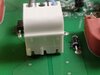
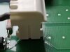
Can anyone help me with the technique to separate this plug and socket combination (the white component in the attached image)?
I am very reluctant to apply any force as I don't want to damage the socket's connection to the circuit board.
Any help/advice will be much appreciated.
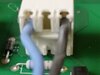
I am very reluctant to apply any force as I don't want to damage the socket's connection to the circuit board.
Any help/advice will be much appreciated.