I'll start off by saying I know next to nothing about electronics. With that said I'm fairly logical and can follow things pretty easily, I'm handy and I can solder just fine.
I'm looking to build a scoreboard used for shuffleboard. What I want it to do is have two separate teams, each with a double digit display which count to 21 then resets. The counting is controlled by a button, which you press once for each point scored. I want to build this as cheap as possible.
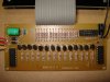
I found online a "counter kit" which counts to "99". With no reset. It was 11 dollars so i figured why not buy it as a starting point since its got a lot of what I want for cheap and without having to do any work. I thought just resetting the power might reset the count to "00" but it doesn't.
I don't really NEED the counter to stop at 21 if i can get it to reset to "00". (Plus with not setting the limit, I could use it for a different score total or a different sport) So my question is: What do I have to do/get to easily make this scoreboard reset to zero?
I'm looking to build a scoreboard used for shuffleboard. What I want it to do is have two separate teams, each with a double digit display which count to 21 then resets. The counting is controlled by a button, which you press once for each point scored. I want to build this as cheap as possible.
I found online a "counter kit" which counts to "99". With no reset. It was 11 dollars so i figured why not buy it as a starting point since its got a lot of what I want for cheap and without having to do any work. I thought just resetting the power might reset the count to "00" but it doesn't.
I don't really NEED the counter to stop at 21 if i can get it to reset to "00". (Plus with not setting the limit, I could use it for a different score total or a different sport) So my question is: What do I have to do/get to easily make this scoreboard reset to zero?