Continue to Site

Welcome to our site!

Electro Tech is an online community (with over 170,000 members) who enjoy talking about and building electronic circuits, projects and gadgets. To participate you need to register. Registration is free. Click here to register now.

  • Welcome to our site! Electro Tech is an online community (with over 170,000 members) who enjoy talking about and building electronic circuits, projects and gadgets. To participate you need to register. Registration is free. Click here to register now.

schematic for Pioneer SA-510

Status
Not open for further replies.

niq_ro

New Member
I need schematic for audio amplifier Pioneer SA-510 ... I found 2 transistor per channel.. made by NEC, but I don't find datasheet for this

D883A = 2SD883A and B773A = 2SB773A ? true or false ? :shock:
 

Attachments

  • NEC.jpg
    NEC.jpg
    11.7 KB · Views: 5,744
I have the same problem with my SA-510. Did you find replacements for these transistors? Does the D883A = 2SD883A and B773A = 2SB773A?
 
You may be able to substitute the following:

2SD883A to 2SC2579

datasheet for original: **broken link removed**

2SB773A to 2SA1104

datasheet for original:
**broken link removed**

the datasheets are not all in English, but the information is there as far as ratings.

I would really try to get an exact replacement, since substituting will require you to adjust the bias, possibly have to alter other values, etc, etc. You may find it is more hassle to substitute and try and get things working again, than to get the originals and maybe only have to make minor adjustments. Also, check the driver transistors they may not have survived the failure of these output transistors.
 
I found a Manual for a SA-500 and a bad schematic for a SA-520
I also found this

**broken link removed**
 
here is the 500 service manual
 

Attachments

  • sa-500.pdf
    829.2 KB · Views: 2,202
Here is the Sa-520 Schematic
 

Attachments

  • 1_101.jpg
    1_101.jpg
    34.4 KB · Views: 4,452
Here is the SA-510 Additional Service Manual But not the Main one.
 

Attachments

  • SA-510HE-HB.pdf
    1.9 MB · Views: 2,006
Hi,

I have the SA-520 which had only the B773A on one channel faulty. I got the 2SA1941 pair and replaced all ouput transistors, only to blow them all, burn one of the bias resistors and blow a speaker, due to the DC passing through the shorted tranny...

I noticed, the website I used to identify the equivalent, did not take into account the Bace-Emitter voltage. Otherwise, the transistor was a good match. The voltage difference is only 1 volt less. My question, will this small difference be the reason why the transistor fries itself? The Veb of the B773A is 6v, I am considdering a transistor with a rating of 7v. This should be ok as long as the Hfe is in the same region right?

I have seen suggestions of the 2SA1104, but they are pricey.

I am considdering:

MJL3281AG with MJL1302AG or 2SA1492 and 2SA3856. If these fry themselves...

BTW, no there aint anything else wrong with the amp. I actually had no fault on the left channel prior to installing the 2SA1941.

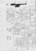
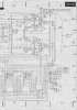
Anyone have the schematic for the SA-520?

Thanks.
 
Here is a Schematic for the Pioneer SA520 Sorry it is not that great but may help.
 
Hi Hotwaterwizard. Thank you for the SM. It seems it would be better to obtain the exact transistors. I came accross a store in UK, which have some stock. I checked every single component, and they are all good. The replacement transistors seemed to have gone into thermal runaway. I see Pioneer used a different Diode matching circuit when they used the 2SA1104 on the SA-540 amp. With some patience, I can probably make the circuit changes, but i thing getting the identical transistors is MUCH easier...

I also see on the circuit Idle current adjustment, which I find strange. There are no adustable resistors in my amp. I have the Euro model.

Have anyone done a repair using different transistors in this one successfully?

Cheers :)
 
Hi,

It seems that I may have a biasing issue. The schematic shows "Idle current adj" I do not find any adjustable components in my amp. Any advise how I have to adjust the bias? I do not seem to have the entire service manual. I find many equivalent transistors, but not the exact ones, so I will have to play with the biasing... Anyone that can tell me how? Thanks.

The bias current adjustment is simply cutting a wire link - which will INCREASE the bias.

If you've fitted other than the exact original transistors then you will probably have to make the bias more correctly 'adjustable' - add a 10K variable resistor between base and collector of the Vbe, the lower it's set the lower the bias

Hi Nigel, Thank you for the advice. Excuse my ignorance, my text books referred as Vbe being "Voltage between base and emitter" will you please draw your suggestion on this? View attachment 63313

I would then like to add, when I had the non-original transistors installed, it worked fine for about five minutes. Could the fact that I did not put in new thermal grease be the cause it went into thermal runaway so quickly at low output? I just bought a new tube, since my daughter thought mine would look great in the carpets... :)
 
Status
Not open for further replies.

Latest threads

New Articles From Microcontroller Tips

Back
Top