PLShutterbug
New Member
Hi -
I'm building a small driveway lighting project, discussed in this thread (and a couple of others here):
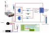
Circuit schematic attached.
My questions:
The circuit required for my project involves:
All will be enclosed in a waterproof ammo-style box, with the battery physically separated from the electronic components with a glued-in wall so I can vent the battery compartment but keep the electronic components watertight.
I had thought to etch a PCB for the circuit, but the only discrete, bare electronic components are the two diodes (1N4001G) between my two PIR sensors and the relay. However, the only real benefit of a PCB is to physically and electrically isolate the two diodes while at the same time ensuring that they cannot touch. Then I thought: rather than go to the trouble of designing a circuit and then deal with caustic chemistry to etch it, why don't I just solder each diode to its PIR sensor's load wire , then attach another wire to the other side of the diode to go on to the relay, and then embed the solder joint in heatshrink tube? It would be far simpler. The question is whether embedding the diode in the heatshrink tube could eventually damage it - maybe the diode gets hot, the tubing prevents the heat from dissipating, and it burns out?
On the advice of the person who helped me in the linked thread above, when I bought the relay I bought one with an included heat sink. They were not physically glued together when I received them and I wonder if I need to use thermal glue when I do attach them. I don't have any ... it would delay the project if I need to order some (I'm rural and no electronics stores close).
Finally, as I ask above I wonder whether the relay really is necessary for my application. My helper in the thread above was driving a LOT more LED strips than I will be so his current draw was higher. I don't know that my circuit will draw enough power to require the high-power switching capabilities of the relay.
Thanks in advance for any advice. This forum has already helped a lot.
I'm building a small driveway lighting project, discussed in this thread (and a couple of others here):
Circuit schematic attached.
My questions:
- is it safe to enclose a 1N4001G diode inside heatshrink tube (effectively using the tube as an insulator)?
- For this relatively low-powered circuit, is the relay really necessary? (My understanding is that the relay effectively boosts a low-powered signal to drive the device on the other side, assuming that device requires more power than the input can deliver.) The PIR sensor load side can deliver 5-100 watts at 12 volts; my 7.5 meter long LED strip will only require 27 watts.
- Assuming the relay really is necessary, must I use thermal paste (like to connect a cooling fan to a PC processor) to attach my relay to the heatsink it came with (the two were not attached; just in the same bag)?
The circuit required for my project involves:
- A solar battery charge controller, which is fully enclosed in its own IP65 plastic box. It has three sets of wires: in from solar panel, in/out with 12v battery, and output load. The charge controller both charges the battery and delivers power either direct from the solar panels or from the battery. Here is a link.
- An SSR-25DD relay with heatsink. Here is a link.
- Two 12v PIR sensors, one on each end of my driveway. Here is a link to the sensors.
- A diode after each sensor. Here is a link.
- Connection to 25' (8 meters) of 12v LED strip lights. Link.
- Battery is a 12v, 7 amp-hour SLA.
All will be enclosed in a waterproof ammo-style box, with the battery physically separated from the electronic components with a glued-in wall so I can vent the battery compartment but keep the electronic components watertight.
I had thought to etch a PCB for the circuit, but the only discrete, bare electronic components are the two diodes (1N4001G) between my two PIR sensors and the relay. However, the only real benefit of a PCB is to physically and electrically isolate the two diodes while at the same time ensuring that they cannot touch. Then I thought: rather than go to the trouble of designing a circuit and then deal with caustic chemistry to etch it, why don't I just solder each diode to its PIR sensor's load wire , then attach another wire to the other side of the diode to go on to the relay, and then embed the solder joint in heatshrink tube? It would be far simpler. The question is whether embedding the diode in the heatshrink tube could eventually damage it - maybe the diode gets hot, the tubing prevents the heat from dissipating, and it burns out?
On the advice of the person who helped me in the linked thread above, when I bought the relay I bought one with an included heat sink. They were not physically glued together when I received them and I wonder if I need to use thermal glue when I do attach them. I don't have any ... it would delay the project if I need to order some (I'm rural and no electronics stores close).
Finally, as I ask above I wonder whether the relay really is necessary for my application. My helper in the thread above was driving a LOT more LED strips than I will be so his current draw was higher. I don't know that my circuit will draw enough power to require the high-power switching capabilities of the relay.
Thanks in advance for any advice. This forum has already helped a lot.