Continue to Site

Welcome to our site!

Electro Tech is an online community (with over 170,000 members) who enjoy talking about and building electronic circuits, projects and gadgets. To participate you need to register. Registration is free. Click here to register now.

  • Welcome to our site! Electro Tech is an online community (with over 170,000 members) who enjoy talking about and building electronic circuits, projects and gadgets. To participate you need to register. Registration is free. Click here to register now.

RV battery isolator

Status
Not open for further replies.

csaba911

Member
Going to make a quick sketch of what I had in mind but first want some input on this.
RV main battery currently have isolator installed but the house side blew up for some reason.
Main battery for engine, cabin, signal, break and head lights only, from here isolator and heavy gauge wire feed to the back battery box (3x deep cycle battery in parallel)
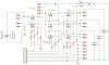
I want to separate the 3 battery and have a charge-discharge controller for it.
Each battery will feed the house independently until reach the cutoff voltage 11.5V
If the engine or the generator running than it would charge them independently until reach full state.
Voltage and current will be measured with 12bit
ADC.
Got 20+ IRFB7530 N channel mosfet (1.2m ohm/190Amp), 0.01 ohm 0.1% 5w dale resistor for current sensing (op amp 30x gain) maximum current draw when all lights and the furnace running is 17Amp (never run everything in the same time)
Without having actual schematics made up I not sure how is the fets body diode will effect the voltage trail.

The reason why I'm planing to separate the 3 house battery because in parallel they always fail after 3-4 years will the main engine battery runs just fine for the 7th year.
 

Attachments

  • Untitled-1.jpg
    Untitled-1.jpg
    62.6 KB · Views: 317
Last edited:
IRF7530 is around 30 mΩ

Battery will be around 10mΩ (ballpark)! and ten thousand Farads
The generator diodes should be rated for peak currents expected, depending on charge level, there could be a 3 V differnce normally when switched,,so use Ohm's Law.

A PWM soft start or an Inrush current limiter of 5A give or take, may help protect devices. ICL's at Digikey are cheap.

ESR on diodes i around 1/W power rating when saturated.

The complex multiplexing wont help if the devices cannot take the surge currents. This depends on Ipk/ Imax margin ratio (Imax on spec). for both pulses and continuous and Rja thermal reistance for cooling.

I would suggest 5 mΩ switches with 20A ICL's and something to prevent rapid on/off/on
 
This are **broken link removed** 1.2 mΩ max
Also will have high side N Fet driver 25v gate voltage. Software is till in framework stage but soft start pwm is possible. What I'm wondering if all the fets gate low and they turned off would the diode in them still carry current ?
 
THe B makes a big difference. my mistake

THe diodes will conduct to protect from inductive + spike from low side source switch off, but if Drain is lower voltage than Source, they will conduct continuously. thus not be good for a dead load switch but ok for a charger.

You may consider a 3 phase MOSFET full bridge from 3 or active loads or sources to 1
But I have not tried this.

Something like this configuration in dsicrete designs will take some effort to understand dead-time, impedance control, surge current etc.
OVP , OTP and OCP protection.
**broken link removed**

Consider the ICL option too.
 
If nothing else at least figured out that much by testing that something drawing 0.177 Amp even if nothing turned on or plugged in. Possibly the onboard (factory) power distribution unit!
It's 12:23 am here so it's a next day project!
 
I had various setups in my boat for the coachouse power, if you dont use a lead acid they tend to sulphate, your better doing a power analysis and only having a little more capacity than you need, then the batteries get cycled and will last longer.

The problem with paralleling batteries like charging the house batt from the engine batt is that when connected together theres a huge current flow to try and balance themselves out, looks like you've addressed that with the circuit idea.

Building a circuit that charges the house batts in a controlled manner is the best way.

Another good idea is make some bracketry and add another alternator to the engine, you can get double sided drive belts for this purpose, then control the alty field windings so the battery gets the correct cycle charge, plus theres no connection to the engine power so nothing engine electrics wise is interfered with so no dead engine battery if something goes wrong.
 
After more testing found out the Refrigerator was drawing the extra current, unplugged sice I only use the gas mode or the ac. I know this not related to my question in any way but I think will just leave it the way is it and have something actually build for more in depth real life testing. My vacation is 2 days away and don't want to take the rv out without being absolutely sure it's working. Maybe next month will build it :)
 
You unplugged the DC from the refrigerator? Does it actually still work? In most trailer fridges the DC is required for the fridge electronics and doesn't actually power the cooling elements.
 
My electrolux fridge was 3 way powered, ac, gas or 12v, the thermostat only worked on gas or ac, on 12v the fridge just cooled constantly and sapped a lot of power, around 100w, if left a while everything froze up.
I've seen boats that have a battery just for the fridge.
You can get cold boxes these days that use peltier heat pumps and are a lot more efficient, and not expensive either.
Like I was saying before you make any changes I'd suggest you do a power survey, work out exactly what you need, in my experience this is rarely done.
 
You unplugged the DC from the refrigerator? Does it actually still work? In most trailer fridges the DC is required for the fridge electronics and doesn't actually power the cooling elements.
You are right, this is a bummer for sure, without dc 12V the gas wont turn on. Probably I can get away with 0.177A draw for 10 days.
 
Status
Not open for further replies.

Latest threads

New Articles From Microcontroller Tips

Back
Top