Continue to Site

Welcome to our site!

Electro Tech is an online community (with over 170,000 members) who enjoy talking about and building electronic circuits, projects and gadgets. To participate you need to register. Registration is free. Click here to register now.

  • Welcome to our site! Electro Tech is an online community (with over 170,000 members) who enjoy talking about and building electronic circuits, projects and gadgets. To participate you need to register. Registration is free. Click here to register now.

running capacitor on modified sine wave inverter output

Status
Not open for further replies.

maicael

Member
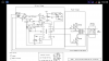
I am constructing a MSW inverter for a friend and he wants me to put a capacitor at the output since he saw it in a circuit.
My question is will this atbleast reduce the harmonics especially when used with fans that buzz.
The circuit says its an optional filter but how efficient will the running capacitor be at the output.
I know it may not be the best as sine waves are the ideal but is this at least ok.
Will the inverter be efficient to a reasonable extent.
What do you guys think?
 
Without seeing the circuit for your MSW inverter it is difficult to say. Could you post it please?

Matt
 
Without knowing what the MSW output stage consists of , what the load is and what the capacitor value is it is impossible to know whether the capacitor would be beneficial or not.
 
Here is the circuit he gave me to build
 

Attachments

  • Screenshot_2015-06-24-19-35-10.png
    Screenshot_2015-06-24-19-35-10.png
    221.2 KB · Views: 618
That is stated to be a PWM circuit but I don't see how the PWM signal is modulated to get a sinewave out (if that is what is intended). :confused:
One way to do that would be to use a 50/60Hz sinewave oscillator to modulate the PWM circuit.
 
That is stated to be a PWM circuit but I don't see how the PWM signal is modulated to get a sinewave out (if that is what is intended). :confused:
One way to do that would be to use a 50/60Hz sinewave oscillator to modulate the PWM circuit.
This is not intended to give out a sine wave but a modified sine wave.what am saying is that the capacitor at the output of the inverter is suppose to kind of clean up the voltage a little bit.
 
A capacitor will likely reduce some of the harmonics, but will also reduce efficiency by creating high current spikes in the output transistors.

What is the PWM circuit doing if it's not to generate a sine-wave? :confused:
 
A capacitor will likely reduce some of the harmonics, but will also reduce efficiency by creating high current spikes in the output transistors.

What is the PWM circuit doing if it's not to generate a sine-wave? :confused:
Ok so is there a way to protect the transistors from this high current spark?
Also am guessing there may be a drop in output voltage due to the capacitors so maybe I could compensate for this one way or the other.
 
Of course a fan will buzz when powered from the output of a modified "sinewave" inverter because the very crude waveform is actually a modified squarewave.
A capacitor on the output will smooth the waveform a little and maybe overload the transistors but the buzz will still be there.
Use a pure sinewave inverter instead.
Pls can you explain a little cleared the part where the capacitor overloads the transistors.
Just want to get a hang on what is going on so I can explain better to my friend
 
The square edges on the modified waveform are at high frequencies. A capacitor is a low reactance at a high frequency that draws a high current that can destroy the output transistors.
A capacitor parallel with the output of your inverter is a short circuit at high frequencies.
 
The square edges on the modified waveform are at high frequencies. A capacitor is a low reactance at a high frequency that draws a high current that can destroy the output transistors.
A capacitor parallel with the output of your inverter is a short circuit at high frequencies.
OK thanks.
I guess am stuck.will have to tell him to use it without the caps
 
I have never needed and have never used an inverter because my electricity is reliable.
 
Status
Not open for further replies.

New Articles From Microcontroller Tips

Back
Top