Continue to Site

Welcome to our site!

Electro Tech is an online community (with over 170,000 members) who enjoy talking about and building electronic circuits, projects and gadgets. To participate you need to register. Registration is free. Click here to register now.

  • Welcome to our site! Electro Tech is an online community (with over 170,000 members) who enjoy talking about and building electronic circuits, projects and gadgets. To participate you need to register. Registration is free. Click here to register now.

Routine for a 12C508 / 509 etc. - SPST switch state detector

Status
Not open for further replies.

timetec

New Member
Hello all - thanks for taking a moment to have a read of this post - you might regret it :)

I've been trying to design a circuit using a 555 & CMOS logic, to perform a 2-state operation using 1 SPST switch.

A few had mentioned in the 'Projects Design/Ideas' sub-forum, that a PIC routine would be a very elegant solution.....

Try to picture a small box with 2 LED's marked A & B - it has a small push-button switch on the lid !


Here's what I want to happen and the logic behind each operation :


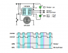
1/ First of all, each time the SPST switch is pressed, a 2 second monostable / timer starts running.

2/ At each switch press, LED A lights for 1 second and then extinguishes.

3/ However, if the switch is pressed TWICE within the 2 second monostable time period, LED B latches ON

4/ Subsequent slow switch presses light LED A for 1 second intervals, however LED B remains switched ON

5/ If the switch happens to be pressed again TWICE within 2 seconds, LED 2 toggles back OFF

6/ Back to 2/

My brain hurts..... :eek:


Required I/O states : Input (switch) and the outputs (A&B) are usually HIGH when inactive (all +5V)

So...... is this dooable with an 8-pin PIC12C508 etc ? - and who's up for a challenge :confused:

Thanks
 
Picbasic / PICaxe

Thanks

Yes, I've already got them - the 50 line 'standard' version of MElabs Picbasic's compiler plus the PICaxe programming editor.

I haven't got a clue where to start, hence the post for some help putting something together :)
 
Here you a little some thing to get you going
Code:
'****************************************************************
'*  Name    : 12f508blink.BAS                                      *
'*  Author  : YOUR NAME HERE                    *
'*  Notice  : Copyright (c) 2009 [select VIEW...EDITOR OPTIONS] *
'*          : All Rights Reserved                               *
'*  Date    : 10/13/2009                                        *
'*  Version : 1.0                                               *
'*  Notes   :                                                   *
'*          :                                                   *
'****************************************************************
 led var GPIO.0
 SW1 VAR GPIO.1
TRISO =%00000010
GPIO =%00000000
Loop:

  if SW1 = 1 then
   GOSUB blinksome
   endif
   goto loop 
blinksome
        High led 
        PAUSE 1000 
        LOw led
        PAUSE 1000 
   RETURN

This is a little more fun then the first code
Code:
'****************************************************************
'*  Name    : 12f508blink.BAS                                      *
'*  Author  : YOUR NAME HERE                    *
'*  Notice  : Copyright (c) 2009 [select VIEW...EDITOR OPTIONS] *
'*          : All Rights Reserved                               *
'*  Date    : 10/13/2009                                        *
'*  Version : 1.0                                               *
'*  Notes   :                                                   *
'*          :                                                   *
'****************************************************************
 i var byte
 led var GPIO.0
 SW1 VAR GPIO.1
 TRISIO =%00000010
 GPIO =%00000000
Loop:

  if SW1 = 1 then
   GOSUB blinksome
   endif
   goto loop
blinksome
        for i=1 to 5
        led = 1
        PAUSE 1000 
        led = 0
        PAUSE 1000 
        next i
   RETURN
 
Last edited:
Code snippets

Thanks very much for the code snippets :)

I can't make Proton IDE lite recognise it - neither set of code will compile.

Proton IDE lite is for PICbasic, however, I can't change the default micro from a 16F628 to a 12F508 (it supports both) :confused:
 
That is picbasic pro you have to buy it I think for the 12f508 you can down load it here
https://www.microengineeringlabs.com/pbpdemo.htm
The demo don't list 12f508 You can use it with 12f683

Proton lite is whole different puppy
This is for proton but it's the 12c508 chip. The hex didn't work on my 12f508
Code:
Device = 12C508

Dim i As Byte
 Symbol led = GPIO.0
 Symbol SW1 = GPIO.1
 TRISIO =%00000010
 GPIO =%00000000

While  SW1 = 1
  If SW1 = 1 Then
   GoTo blinksome
   EndIf
   
blinksome:
        For i=1 To 5
        led = 1
        DelayMS 1000   
        led = 0
        DelayMS 1000  
        Next i
   
Wend
No they don't support 12F508
I can't change the default micro from a 16F628 to a 12F508 (it supports both)

You have to buy it
 
Last edited:
May I ask what's the purpose of this device?

:) You can and I'll tell you :

It's to start / stop and reverse (when required), the direction of H-bridge logic controlled motor, on a piece of lab equipment.

The catch is, this all has to be done using just a simple SPST push-button switch.... :eek:

Cheers
 
What you posted don't add up to that have fun learning to write code I'm not writing the whole thing in basic just some samples but to let you Know there is no free basic compiler for 12f508
 
Last edited:
Great Cow Basic or GCBasic will work with12f508 and other baseline PICS, including the 10F's. Have to be careful with the 12C, 16C series though, because no one hardly uses them anymore and therefore not always tested.
 
Thank you for the explanation . Would that application require additional logic, for example, would you stop the motor before changing direction?

Would you consider a "short" and "long" dual-switch function instead? Here's how it works. You press the switch and get a short beep as feedback. If you release the switch before one second you'll toggle the "short" press output from off-to-on or from on-to-off. If you press the switch and hold it pressed until you hear the double-beep feedback at one second and then release it you'll toggle the "long" press output from off-to-on or from on-to-off. You might use the "short" press output for motor on/off and the "long" press output for direction. You can also add the logic to ignore a "long" press to change direction if the motor is on.

In the diagram below you'll notice we use a switch state latch or memory (swold) which allows us to easily detect a "new press" or a "new release" while ignoring the other switch states. We sample the switch at 32-msec intervals to debounce it. On a "new press" we start a 1-second timer (the blue sections) and task a single beep for user feedback. On a 1-second timeout (the red vertical lines) we task a double beep for feedback. On a "new release" we check to see if the timer has timed out and then toggle the appropriate "short" or "long" press output. Please note that the diagram assumes we've added logic to prevent changing direction if the motor is running (active low).

Regards, Mike

on-off-dir-png.34393
 

Attachments

  • On-Off-Dir.PNG
    On-Off-Dir.PNG
    19.3 KB · Views: 4,074
Last edited:
Mike that looks good easy to code

Nick Great Cow Basic or GCBasic hasn't had a update in over a year I wouldn't tell a beginner to try them.
Learn it and then it's gone
 
Last edited:
It is pretty easy to code Burt...

Code:
;
;  while(1)
;  { beeptask();                // 32-msec beep or delay
;    swnew = ~gpio;             // sample active lo switch GP3
;    if(swnew.3 == 1)           // test for "new press"
;    { if(swold.3) == 0)        //
;      { swold.3 = 1;           // update switch state latch
;        swtmr = 1000/32;       // start 1 second timer
;        beep = 1;              // task a single beep
;      }
;    }
;    if(swnew.3 == 0)           // test for "new release"
;    { if(swold.3 == 1)         //
;      { swold.3 = 0;           // update switch state latch
;        if(swtmr)              // if "short" press
;        { gpio ^= 1;           // toggle GP0 "motor" pin
;          swtmr = 0;           // turn off 1 second timer
;        }                      //
;        else                   // else "long" press
;        { gpio ^= 6;           // toggle "direction" pin and LED
;        }
;      }
;    }
;    if(swtmr)                  // if 1 second timer running
;    { swtmr--;                 // decrement it
;      if(swtmr == 0)           // if timed out
;      { beep = 3;              // task a double beep
;      }
;    }
;  }
The assembly language version complete with beep task code (below). A plain old delay is 32-msecs. If the 'beep' variable is '1' you'll get a 32-msec 500-Hz beep instead. If the 'beep' variable is '3' you'll get a 32-msec 500-Hz beep followed by a 32-msec delay followed by another 32-msec 500-Hz beep (96-msecs total).

Code:
debounce
        movlw   32              ; debounce/beep delay
        movwf   mstmr           ; msctr = 32 msecs
        movlw   b'00010000'     ; mask for GP4 spkr pin
        btfsc   beep,0          ; beep? no, skip, else
        xorwf   GPIO,F          ; toggle spkr pin
        inDlyCy(1000*usecs-6)   ; 1-msec minus 6 cycles
        decfsz  mstmr,F         ; done? yes, skip, else
        goto    debounce+2      ; loop
        movf    beep,W          ; beep task running?
        bz      newsample       ; no, branch, else
        decfsz  beep,F          ; beep task done?
        goto    debounce        ; no, branch (loop), else
newsample
        comf    GPIO,W          ; sample active lo switches
        movwf   swnew           ; save sample
newpress
        btfsc   swnew,3         ; swnew.3 == 1 and
        btfsc   swold,3         ; swold.3 == 0 (new press)?
        goto    newrelease      ; no, branch, else
        bsf     swold,3         ; update swold.3 state latch
        bsf     beep,0          ; task a single beep and
        movlw   1000/32         ; start 1 second timer
        movwf   swtmr           ;
newrelease
        btfss   swnew,3         ; swnew.3 == 0 and
        btfss   swold,3         ; swold.3 == 1 (new release)?
        goto    timeout         ; no, branch, else
        bcf     swold,3         ; update swold.3 state latch
        movf    swtmr,W         ; timed out "long" press?
        bz      long            ; yes, branch, else
short
        clrf    swtmr           ; turn off switch timer
        movlw   b'00000001'     ; use GP0 pin mask to
        xorwf   GPIO,F          ; toggle GP0 'motor' on/off output
        goto    debounce        ; 
long
        movlw   b'00000110'     ; use GP2 & GP1 pin mask to
        xorwf   GPIO,F          ; toggle 'direction' output and LED
        goto    debounce        ;
timeout
        movf    swtmr,F         ; switch timer running?
        bz      debounce        ; no, branch, else
        decfsz  swtmr,F         ; is it timed out?
        goto    debounce        ; no, branch, else
        movlw   3               ;
        movwf   beep            ; task a double beep
        goto    debounce        ;
;
 
Last edited:
That looks great what C would you use to compile for a 12F508
HI-TECH will
 
Last edited:
I would use assembler for the 12F508/12F509 Burt. I only put that pseudo C code there for the "assembler impaired" (lol).
 
Nick Great Cow Basic or GCBasic hasn't had a update in over a year I wouldn't tell a beginner to try them.
Learn it and then it's gone
Yea, it was more of a statement about free compiler for baseline devices. It has had a major update this year, but will let people make their own decisions as to what is appropriate.
 
A huge thanks Mike - you've obviously put a lot of time into this.

I don't think the 'long press' to select reverse is actually a good idea... Why ? - because when a person naturally wants to perform a definative action (in this case, stop a wildy-spinning motor), they are more likely to hold the button down for a much longer period of time, in order to stop it.

This is illogical to you & I, because we know the processes involved & the switching timing, but not to the layman.

Is the 1st code listing you posted in Picbasic ? - I get lots of errors when I try to compile it in any of the 'freebie' basic compliers I have. :confused:
Unfortunatly, the same with 2nd assembler listing - I attempted to compile this with MPASM - but just got of 'not defined' errors...

In saying that, I'd love to give your code a try - would any changes be needed to use a 12F509 ? - no 635's anywhere !

Please forgive my total & utter ignorance :eek:
 
The first code snippet is pseudo C code. The second code snippet is assembler but you shouldn't expect it to compile until you add missing pieces like variable declarations, an init' section, the delay macro, etc.

No promises but I'll try to come up with something for 12F509 when I get a chance.

Mike
 
"the first code snippet is pseudo C".... Yes, that certainly explains the problems encountered using a PICbasic compiler ! :D

Did think the assembler code looked a bit 'out of character' from the few asm listings I have looked at -- seem to remember there's usually quite a bit of text & code before the actual routine itself starts....

Cheers Mike :)
 
Status
Not open for further replies.

Latest threads

New Articles From Microcontroller Tips

Back
Top