rafael_cordeiro
New Member
Hello everybody,
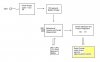
I am building a robot with 3 wheels, where two of these are powered independently. I am currently building the power source circuits. I made a diagram, which represents the hole idea, and it follows attached to this message. I am thinking to make a single printed circuit board for this circuit.
I would like to hear any comment from anyone that think that can help me somehow, in order to evaluate this idea.
The main idea behind this circuit is that when I need to recharge the batteries, I must only plug a wire on the walls mains source. When it is charged, I would unplug it, and let the robot run. The thing is, to avoid the batteries being discharged thru the charger circuit, I am thinking about using some diodes before the battery. What do you think? But then I think I must increase the voltage due to the tension losses inside the diode. is that right?
Well, I'd appreciate any help on the subject.
Greetings,
Rafael Vasconcelos