Continue to Site

Welcome to our site!

Electro Tech is an online community (with over 170,000 members) who enjoy talking about and building electronic circuits, projects and gadgets. To participate you need to register. Registration is free. Click here to register now.

  • Welcome to our site! Electro Tech is an online community (with over 170,000 members) who enjoy talking about and building electronic circuits, projects and gadgets. To participate you need to register. Registration is free. Click here to register now.

RGB LEDs without PWM ?

Status
Not open for further replies.

2camjohn

Member
Hi Guys,

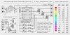
I want to drive an RGB LED from a PIC that doesnt have hardware PWM.

I dont exactly need 255 colours, just 8 - 10 cool ones would do...

I have 4 IO pins spare. I am trying to work out the best way of multiplexing these pins, with resistors to give me a good range of colours??


If anyone has any good websites on this I would really appreciate it.
I have tried google but everything refers to controling RGB LEDS with PWM.


Cheers
John
 
Regardless of anything, you NEED PWM to do this, where you're getting confused is between hardware PWM (most PIC's only have one or two of these - or none), and software PWM, which is available on any PIC.

Someone (I forget who) has posted his circuit with an 8 pin PIC feeding LED's - perhaps he'll read this and post his software as well?.
 
Ah OK thanks.

I know about hardware and software PWM, but I cant get software PWM to work and dont have a scope to test what is wrong..


I thought I saw a circuit somewhere where someone used the series resistors to create colours, EG if you want green to be 50%, then use a series resistor to limit green to 50% of its max current.


Maybe I imagined it.

Ah well....
 
Well, you could. If a 100 ohm resistor makes the green take as much current as it can take, if you instead put a 200 ohm resistor on 2 different pins, both going to the green, then you get 2 different intensities when you turn on one pin versus both pins.

But it's completely unnecessary. Software PWM is hardly difficult.
 
2camjohn said:
I thought I saw a circuit somewhere where someone used the series resistors to create colours, EG if you want green to be 50%, then use a series resistor to limit green to 50% of its max current.

I think Mike K8LH posted something along those lines a couple of weeks ago... maybe try to search his posts?
 
not sure what language you use, but here's my working solution (a recent project) in BoostC.

essentially it's a 2-channel RGB LED controller, where either channel either accepts a color value via serial (0-255, fades from red to green to blue, with of course all colors in between), or shows a fixed color chosen by holding down a button.

Code:
void PWM_cycle()
{
	char a;
	RLED1=0; GLED1=0; BLED1=0;
	RLED2=0; GLED2=0; BLED2=0;
	for(a=0; a<255; a++)
	{
		if(a>=r1val)
		{	RLED1 = 1;	}
		if(a>=g1val)
		{	GLED1 = 1;	}
		if(a>=b1val)
		{	BLED1 = 1;	}
		if(a>=r2val)
		{	RLED2 = 1;	}
		if(a>=g2val)
		{	GLED2 = 1;	}
		if(a>=b2val)
		{	BLED2 = 1;	}
		delay_10us(5);
	}
	checkserial();
}

that's my entire PWM routine. (note i was using common anode LEDs so 0=on, 1=off) calculating the values for the **val variables is a separate task, not difficult, but unimportant for getting the PWM working... but really, the PWM function is extremely simple, you should definitely try to get it working. even if you're not using C, it should be fairly obvious what's going on there, and not very hard to replicate it in whatever language. the one disadvantage is that it does require the PIC to spend most of its time running the routine to generate the PWM.

trying to do it with multiple resistors is going to require tons of I/O just to control one LED. if your application makes it impossible to be constantly running a routine to generate PWM cycles, then perhaps you should program a second PIC to handle that, and send it the desired color via serial... you know, exactly like what I made :lol:
 

Attachments

  • rgbledcon.c
    4.3 KB · Views: 741
Hi Guys,

Evandude's example is excellent... I plan on doing pretty much the same thing but from within an interrupt service routine... Here's my design concept (below) which I hope to wire up during the long Thanksgiving Holiday weekend...

Full duplex bit banged serial I/O with 16-byte circular receive and transmit buffers is accomplished using 3X bit rate interrupts (google "16F819 Serial" for an example on PICList) and I'll use that same interrupt cycle/rate to drive the PWM counters and LEDs...

Regards, Mike
 

Attachments

  • rgb2.jpg
    rgb2.jpg
    100.1 KB · Views: 6,331
hi im shoghi!!

im able to use pic16f873 and set it to pwm mode, but it can controll only one led,the problem is i wan to controll 3led using that one available pwm output, i wan to do RGB color changing project for my car dashboard.i very new to pic..i noe assembly only abit..any idea how to use that one pwm to controll rgb leds and get the color i want myb by switch


Do anyone have done before any projects regarding to RGB LED controll.controlling 3 leds, RED BLUE and GREEN using a microcontroller to generate any color v want preferable by pressing a switch mybe.if u hav done a ny similiar projects..a simple RGB LED controller would be sufficient for me.i noe assmebly language only,tht also just beginner stage, if u hav can u gv me the shcematics and assembly codes where i could take it and study it and built the controller and understand more abt it and later i could expand the controller.
thanking in advance and
wt rgds

shoghi:) anniyan_x@yahoo.com
 
Last edited:
1)
With 4 pins left, you could drive three 74hc595 io expanders (daisychained) ... each one gives you 8 bits, so you could hang a resistor ladder off each to vary the amount of current your RGB is receiving.

2)
There are 4 bit and 8 bit (brightness levels) rgb led drivers from philips (or whatever they're called now) which you control from 2 pins (i2c) ... they handle all the pwm nity-grity, you just throw numbers at 'em

3)
Maxim has a 28+ port linear led driver which is also i2c... the chip sets the current level for each connected LED up to a maximum level set by a programming resistor.
 
Rgb Led

philba said:
actually, go look at evan dudes example. it is exactly what you want. forget about HW PWM.

actualy i can program in assembly language only currently and after tis only i thk i learn C. anyway does any here could glady provide me with simple RGB led circuit and codes using microcontrollers were v can generate different colors any colors,no matter randomly or what.im now currently looking into how make software PWM and write the codes to controll 3 led red blue and green and generate any color v want.

ps:-i hav basic fundamental knowledge in PICS and could understand written codes better rather than writing a new one myself:eek: but im into studying now and learning procees.
 
Status
Not open for further replies.

Latest threads

New Articles From Microcontroller Tips

Back
Top