Continue to Site

Welcome to our site!

Electro Tech is an online community (with over 170,000 members) who enjoy talking about and building electronic circuits, projects and gadgets. To participate you need to register. Registration is free. Click here to register now.

  • Welcome to our site! Electro Tech is an online community (with over 170,000 members) who enjoy talking about and building electronic circuits, projects and gadgets. To participate you need to register. Registration is free. Click here to register now.

RFC Solar Cgarge Controller

Status
Not open for further replies.

MrUmunhum

New Member
RFC Solar Charge Controller

Hi group.

I put together what I like is a simple Solar Charge Controller. I would like you to examine it and tell me if you think it will work?

The therory of operation is:
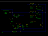
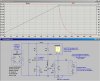
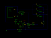
  • Power comes from the solar panels
  • The TIP2955 pass power when they are grounded
  • The LM317 creates a reference voltage of 13,7 volts
  • If the battery voltage is over 13.7 volts the LM741 shorts the TIP2955 ground
I am concerned about R1, is it placed correctly and is it the right value?
What do you think?
This is another one of my "Monkey See. Monkey do" projects.:)
 

Attachments

  • Solar_Controller.png
    Solar_Controller.png
    7.4 KB · Views: 289
Last edited:
What is the max base current will ever get to the power transistors?(Hint: Ohms law)
How do you guarantee that current is shared equally by the power transistors?
Why regulate the supply pin on the 741? (Hint: look up PSRR).

How much current is your panel capable of?

I can show you how to do this with about 5 components, but first you have to answer my questions.
 
Last edited:
What is the max base current will ever get to the power transistors?(Hint: Ohms law)
How do you guarantee that current is shared equally by the power transistors?
I forgot the resistors. A 0.1 ohm 5W resistor in each input leg of the TIP2955. So is that the answer you are looking for? Remember, I'm a software guy not a double E.
MSMD( Monkey see, monkey do ).

Why regulate the supply pin on the 741? (Hint: look up PSRR).
I though that a lower voltage would be better to keep the heat down?

How much current is your panel capable of?
Dead short, 3 set of 3 panels produce appox 18 volts at 18 amps. Monitoring the charge current the most I see is 11 amps. Have not monitored the input voltage.

I can show you how to do this with about 5 components, but first you have to answer my questions.
I'm listening! :)

My web resources:
 

Attachments

  • Solar_Controller.png
    Solar_Controller.png
    9.2 KB · Views: 257
Last edited:
Here is a variation of regulator I came up with for a linear power supply/battery charger. When I said five parts, I thought you could use a shunt regulator, but at 12A and 14V (168W) that is not practical. I know this series regulator works because I have already built it.

For your solar panel, I crudely modeled it as a current source of 12A, shunted by a voltage to clamp it's open circuit voltage at near 18V. I modeled your battery bank as though it is a 12V flooded-cell lead-acid battery which is charged at 14.25V. I included a realistic series resistance. For simulation purposes, the 50 Farad capacitor charges about a factor of 100 times faster than your actual battery will charge. So in the real world, seconds become hours :D

Note the power dissipation in the PFET. It has to be mounted on a very large heat sink. Or you may mount it on a surplus CPU heatsink with integral 12Vdc fan.
 

Attachments

  • SolarRegDiss.jpg
    SolarRegDiss.jpg
    161.3 KB · Views: 183
  • SolarReg.jpg
    SolarReg.jpg
    273.5 KB · Views: 232
Last edited:
damit! now I am stuck in a loop!

I think what he ment was to start a new thread in the main area not in an older thread.
 
Status
Not open for further replies.

Latest threads

New Articles From Microcontroller Tips

Back
Top