Imagine a hoop, made out of flat copper strip, about 3" wide, tens of feet long. There are tens of Amps of RF current (3-15MHz) flowing along the strip. Do you use 3" or 6" (one side or both sides of the strip) when figuring the cross-section of the surface that the RF flows along?
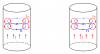
Suppose you wrap the strip around a plastic pipe formed into a loop (like a hula-hoop) as a mechanical support, such that the strip wraps three-fourths of the way around the pipe, leaving a gap between edges of the strip. Has anything changed? Where does the current flow?
Now, suppose you wrap the strip around a smaller diameter plastic loop, such that the copper strip actually closes over itself, and you solder the seam? You have effectively made a tube over a plastic mandrel. Does the RF current still flow on both the outside of the tube and inside of the tube, or only on the outside?

") ) ... Are there any freeware EM modelers out there?
) ... Are there any freeware EM modelers out there?