Continue to Site

Welcome to our site!

Electro Tech is an online community (with over 170,000 members) who enjoy talking about and building electronic circuits, projects and gadgets. To participate you need to register. Registration is free. Click here to register now.

  • Welcome to our site! Electro Tech is an online community (with over 170,000 members) who enjoy talking about and building electronic circuits, projects and gadgets. To participate you need to register. Registration is free. Click here to register now.

RF based soil moisture detection with capacitance based probes

Status
Not open for further replies.

earckens

Member
I am looking to make a capacitive soil moisture sensor; having looked at all possible kinds of detectors I found that this soil moisture detector should meet the following requirements:

1. hardware based (not involving any controller programming)
2. not based on measuring resistivity or using currents: even with AC and stainless steel probes this leads to corrosion over time
3. RF based using capacitive probes (no use of current, see 2)
4. frequency range 100MHz +/- 50MHz (to avoid influence of soil minerals)
5. output voltage within 0 to 5V range, but not required to extend to this full range
6. sensor probes must be able to be self-made, ie. PCB board (see attached files)

Some research dug up the following coverage: https://www.edaboard.com/showthread.php?t=353365 (the relevant thread is closed and the original author cannot be found)
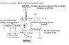
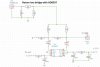
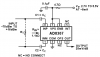
Using an AD8307 RF logarithmic amplifier and a LTC6905 100MHz oscillator.
Questions:
1. I have a hard time locating for purchase this LTC6905 oscillator. Is there an equivalent way to produce, with a single IC, a 100MHz square wave signal 50% duty cycle with an output driving a 600 ohm load, rail-to-rail?
2. In attachment you find some design considerations, copied from the original thread: would you please have a look at those and let me know your comments re. feasibility, corrections,..?

Thank you!
Erik
 

Attachments

  • return loss bridge.jpg
    return loss bridge.jpg
    114.7 KB · Views: 390
  • return loss  circuit.JPG
    return loss circuit.JPG
    121 KB · Views: 345
  • AD8307Circuit.png
    AD8307Circuit.png
    23.3 KB · Views: 291
  • rf capacitive probe- return bridge loss 1937.pdf
    433.5 KB · Views: 230
Hi ronsimpson, it says discontinued at Digikey. But such oscillators tend to have high output impedance, ie they are used to drive an amplifier, not a load.

In my case I need an output impedance of about 500 to 600 ohm, because a AC Wheatstone bridge will be driven where one of the LC legs will have a varying capacitance, hence a varying load while the source (oscillator) needs to give a stable output in frequency terms and in dBm terms.
 
The one on aliexpress is the programmable one, chip marking is LTBJC, per datasheet from LTC. Set of 10 ordered (EUR10,30 shipping inc.)
Now we are set to start experiments after parts arrival (about 8 weeks).

Having had no reply on my thread opener question I assume I will need to be more specific. So, detailed questions will follow as soon as I have an experimental setup, hoping to get more response then :)?

Grts,Erik
 
Having had no reply on my thread opener question I assume I will need to be more specific. So, detailed questions will follow as soon as I have an experimental setup, hoping to get more response then :)?

Grts,Erik
I'm not sure you actually asked any questions, just stated your requirements
 
I'm not sure you actually asked any questions, just stated your requirements
Sorry for the obfuscation in my initial post; the last sentence did ask for a review of my proposal for possible errors or evaluation of feasibility, probably this is too broad a question?
 
A few comments:

The idea of using a return loss bridge for measuring capacitance seems rather odd.
It may well be OK, but it is not something which I would have considered.

When I have used return loss bridges, I have always used a sinewave for the excitation voltage.
Using a squarewave sounds like a bad idea because the capacitance being measured will have a different reactance at each of the frequency components (harmonics) in the squarewave. This may lead to a poorly defined balance in the bridge.

JimB
 
The idea of using a return loss bridge for measuring capacitance seems rather odd.
I was just trying to say the same thing.
Some of the moisture detectors show a wide range in capacitance. I would make a RC oscillator and count the frequency. Many people would use a LM555 as the oscillator. I might think about a simple voltage comparitor (with positive feedback) oscillator. If you really want "high frequency" then choose a low value resistor and shoot for 1mhz.
 
A few comments:

The idea of using a return loss bridge for measuring capacitance seems rather odd.
It may well be OK, but it is not something which I would have considered.

When I have used return loss bridges, I have always used a sinewave for the excitation voltage.
Using a squarewave sounds like a bad idea because the capacitance being measured will have a different reactance at each of the frequency components (harmonics) in the squarewave. This may lead to a poorly defined balance in the bridge.

JimB
Good observation. There is no actual need to stick to a square wave, the reason for that choice is the use in the intial project. If a sine wave 100MHz generator is available I would gladly use that: is there any suggestion for that choice of generator?
 
Update on this post:
I ordered and received an oscilator from LTC. I had ordered the LTC6905, programmable version (LTBJC: resistor between 10k and 25k sets the output frequency).
However, I get max 10.6kHz rail-to-rail, when pin 4 to GND, same when "open"; this should have given me respectively /4 and /2 divisions. When pin 4 to +5V (should be /1) I get a frequency adjustable sinewave of 90 to 150MHz, but not rail-to-rail it now is 4V to 5V peak-to-peak.
The sine wave I can understand because I use no shielding nor proper BNC connectors. But why not rail-to-rail, and why do the division settings /2 and /4 not work properly?
Either this is not the 17MHz-170MHz chip, or I am doing something wrong in my measurements.

Anyone to give me some advice please?
 

Attachments

  • DC2073A-2-F.pdf
    34.4 KB · Views: 267
  • DSC_1126.JPG
    DSC_1126.JPG
    1.5 MB · Views: 189
  • LTC6905 resistor set frequency SOT-23 oscillator.pdf
    170.7 KB · Views: 155
  • DSC_1125a.jpg
    DSC_1125a.jpg
    1.1 MB · Views: 192
You are trying to measure a 90 to 150MHz square wave, using a 50MHz oscilloscope.
You will not get any sensible display on the oscilloscope.

JimB
 
This scope has firmware updated for 100MHz
That sounds strange.

If you have a real 100mhz scope and you looked at a 5 volt P-P 100mhz square wave signal you should see a sign wave (almost sign) with a P-P of 3 to 4 volts. You will not see a square wave.
You will not see 5V p-p.

Look at the "1/2/4" pin and see what the voltage is. Can you change it?
 
Would it be because of the stray capacitances of the probes, the non-adjusted load impedance and the oscilloscope working on its bordercapacities (the Rigol has been upgraded with new firmware to the 100MHz version) causing any square wave output to be distorted to a smaller PtP level sine wave?
If that is the case, then I might indeed yet have the correct frequency version of the LTC chip?

The divider pin #4 receives either +5V, 0V, or hanging in the air as per the data sheet; but still no correct divisions by 2 or by 4. Any clues maybe?
 
Status
Not open for further replies.

Latest threads

New Articles From Microcontroller Tips

Back
Top