Continue to Site

Welcome to our site!

Electro Tech is an online community (with over 170,000 members) who enjoy talking about and building electronic circuits, projects and gadgets. To participate you need to register. Registration is free. Click here to register now.

  • Welcome to our site! Electro Tech is an online community (with over 170,000 members) who enjoy talking about and building electronic circuits, projects and gadgets. To participate you need to register. Registration is free. Click here to register now.

Review Zero-Cross Detector Please

Status
Not open for further replies.

dknguyen

Well-Known Member
Most Helpful Member
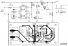
Merry Christmas! This circuit is supposed to detect a mains zero crossing so that a PIC can count them and use it as a timkeeping oscillator.

My thinking (since the rest of my circuit is isolated from the full mains voltage anyways) is that after the mini stepdown transformer it shouldn't be too dangerous to work with the signals. The transformer only steps down the voltage to 6Vrms and the comparator can only accept ~4V or so max so the resistive divider is supposed to reduce step down that voltage again. I can't seem to make the resistive divider symetrical (two m's?) since I need (or want to) ground one output terminal of the transformer (to the DC supply) so that the common mode voltage doesn't exceed the comparator input range. At the same time though, I want to connect the - terminal of the comparator to that same ground to use the "zero voltage" as the comparator's threshold, so I can't separate the bottom terminal of the comparator and transformer in any way (like a resistor to make the divider symmetrical). If I do it the way shown, both Rs have to be the same or the reduction will be lopsided. Can anyone think of a better approach (assume I can't get another transformer to step down the voltage more)?

If the output of the comparator is unipolar it's all good. But the diode and resistor is because I'm assuming the comparator is bipolar. The diode is to clamp out the negative voltage before it gets read into the microcontroller's "change of state interrupt" pin and the pulldown resistor is there to allow a LO to be signalled since the diode stops the comparator from outputting a low.

Does anyone see anything wrong or improvements for this circuit? Like currents from the transformer flowing into the rest of the DC system through the ground or anything like that?

Thanks.
 

Attachments

  • Timer.gif
    Timer.gif
    16.3 KB · Views: 1,126
Last edited:
Looks rather over complicated?, how about this, which is the normal way of doing it. The voltage regulator isn't anything to do with it, but would normally be there to feed the micro.
 

Attachments

  • zero_cross.gif
    zero_cross.gif
    3.8 KB · Views: 1,895
Wouldn't the voltage drop across the bridge rectifier diodes be too great if the transformer was outputting 6V? It would clamp down the rectified AC waveform enough so that the zero crossings aren't spaced apart very evenly anymore? That's the problem I was running into when using diodes so I was trying to avoid that.

I was also having a bit of trouble trying to decide what threshold to use for a rectified signal since there's only one instaneous point where it actually hits zero (if even that due to possible noise). That's the second reason I wasn't using a bridge diode.

Baseless concerns?
 
Last edited:
dknguyen said:
Wouldn't the voltage drop across the bridge rectifier diodes be too great if the transformer was outputting 6V? It would clamp down the rectified AC waveform enough so that the zero crossings aren't spaced apart very evenly anymore? That's the problem I was running into when using diodes so I was trying to avoid that.

I was also having a bit of trouble trying to decide what threshold to use for a rectified signal since there's only one instaneous point where it actually hits zero (if even that due to possible noise). That's the second reason I wasn't using a bridge diode.

Baseless concerns?

Yes, baseless concerns - the simple circuit with the bridge gives a pulse starting just before zero-crossing and ending just after. It's simple to add a slight delay to exactly hit zero-crossing if you really want to, normally it would be done in the software.
 
dknguyen said:
Wouldn't the voltage drop across the bridge rectifier diodes be too great if the transformer was outputting 6V? ?
No, the transformer output would have to be at least 9 Volt peak in order for there to be enough voltage for the voltage reg. This is more than adequate to turn the transistor on.
dknguyen said:
It would clamp down the rectified AC waveform enough so that the zero crossings aren't spaced apart very evenly anymore? That's the problem I was running into when using diodes so I was trying to avoid that.?
I don't see why it would but it does not matter if it does. The average frequency output by the transistor will be 2F where F in the mains frequency. A few milliseconds of jitter won't matter.

dknguyen said:
I was also having a bit of trouble trying to decide what threshold to use for a rectified signal since there's only one instaneous point where it actually hits zero (if even that due to possible noise). That's the second reason I wasn't using a bridge diode.?
It does not matter what the threshold is. The threshold could be at say 3 Volt. All you need is a circuit that provides a pulse at 2F.
dknguyen said:
Baseless concerns?
Yes.
 
Oh wait, I get it. The two pulses don't have to be evenly spaced for it to work correctly. You get two pulses, that means one 1/60th second has passed, whether or not the pulses are spaced T/2 apart or if they microseconds apart. It just means you can't count in 1/120ths of a second...but who cares about that. I'm still thinking in terms of AC switching.

Plus I get to use a bridge rectifier! I dunno...I just like the way it works where the current travels along different paths but comes out the same way.

THanks.

EDIT: How noisy are AC lines? Is hysteresis needed? How would you go about adding that to the transistor if you wanted to? THe schmitt trigger circuit in my digital logic course comes to mind but I'm pretty sure it was CMOS and not just a lone NMOS.
 
Last edited:
Another ideas for zero crossing detectors wich I made.
3 attached files:
-zerocross1.png (version 1)
-zerocross2.png (version 2)
-wave.jpg (output signal waveform)
 

Attachments

  • zerocross1.png
    zerocross1.png
    12.2 KB · Views: 1,251
  • zerocross2.png
    zerocross2.png
    13.2 KB · Views: 1,051
  • wave.jpg
    wave.jpg
    16.2 KB · Views: 733
Hmmm, that's really neat use of the diode rectifier and opto-isolator, and without the transformer I would think it would work at both 120V or 230V assuming the opto isolator is rated right Hmm.
 
In my country, the line voltage is 230V-50Hz.

The 120V line voltage is an advantage for this circuit,
because disipated power on resistor R1 is smaller.
 

Attachments

  • photo1.jpg
    photo1.jpg
    32.5 KB · Views: 697
  • photo2.jpg
    photo2.jpg
    16.6 KB · Views: 565
What's wrong with using the PIC's timer?

The crystal oscillater driving the PIC normally has a stability of at least 30ppm which is good enough for most purposes.

You know how much I don't like using the mains frequency as a time base, yes I know it's accurate until you take your project on holiday to somewhere with a different or less stable frequency.
 
I usually work with mobile robot-types so I don't get a chance to mess around with what you can do when you are being powered by the mains. This is a reflow oven controller and this is supposed to be for the timer. I don't think a PIC has a crystal built into it, unless you are talking about an external crystal (which I do on all my robots anyways so I'd like to try something new).
 
I'd just use a crystal with the PIC. even 60 ppm is better accuracy than you need.

The only reason I see to do zero crossing is for phase control of triacs.

By the way, em2006, those circuits seem more complex than you need. I'd use one H11AA (or similar) opto and Schmitt trigger into the PIC. You will still get both ZCs of a complete cycle.
 
I'm using TRIACs, but the PIC isn't switching them. It just sends a signal to an analog driver chip that becomes activated whenever both the PIC is sending a signal and the AC voltage crosses zero...really neat the way it works actually- quite ingenius!. So yeah this clock thing is just something in excess.

The project is already so straightforward (hardware-wise at least) that I want to do something extra on it...otherwise it's just a PIC reading thermocouple data via SPI and setting a pin to be high or low.

My biggest problem right now is deciding on what to use for an interface. I want to be able to graph the ideal temperature profile and superimpose it on the actual temperature as the whole thing goes along so I need a pretty big graphic LCD, and a keypad or something to set the temperature profile. Problem is I hate working with buttons and screens and have never before needed to make something with a user interface.
 
Last edited:
dknguyen said:
I'm using TRIACs, but the PIC isn't switching them. It just sends a signal to an analog driver chip that becomes activated whenever both the PIC is sending a signal and the AC voltage crosses zero...really neat the way it works actually- quite ingenius!. So yeah this clock thing is just something in excess.

The project is already so straightforward (hardware-wise at least) that I want to do something extra on it...otherwise it's just a PIC reading thermocouple data via SPI and setting a pin to be high or low.

My biggest problem right now is deciding on what to use for an interface. I want to be able to graph the ideal temperature profile and superimpose it on the actual temperature as the whole thing goes along so I need a pretty big graphic LCD, and a keypad or something to set the temperature profile. Problem is I hate working with buttons and screens and have never before needed to make something with a user interface.

could you post more info on the triac control circuit. sounds interestring.

I'm thinking about doing a reflow oven myself and my approach is to use a PC via serial or USB for the charting/control. the idea is to allow stand-alone operation but plug in a PC for more detail and downloading profiles. What I'd really like is a LAN interface via a web page. My current design uses an F88 to directly control the heater TRIAC, a couple of buttons and drive a char mode LCD display. The idea is to use PID to get better control over the profile.
 
philba said:
could you post more info on the triac control circuit. sounds interestring.

sounds like he's using something like the MOC3031 ... it's a zero crossing triac driver, to interface low voltage DC logic with high voltage ac control
 
That's exactly what I'm using!

Basically everything I Know about triacs and the driver comes from that datasheet and the app note that goes along with it.

https://www.fairchildsemi.com/an/AN/AN-3004.pdf#page=1

I personally think it's really neat that the thing draws its drive power from the AC line and not the optocoupler so you can use it to power a disproportionately larger TRIAC.

Maybe I should do a PC interface...but I don't like GUI programming hehe and I want a graph to show up somewhere.

It's probably going to be a curing oven at 60 degrees most of the time more than a reflow oven for me. I just like to conformal coat my boards. Maybe it'll be for reflow when I come by a particularly nasty QFN IC or a BGA or something. Maybe I'll have hot-air by then? Maybe not. I just don't like solder paste (but I guess hot air uses that too).

I did find a silicon oscillator with a frequency of 1Hz though...maybe I'll just use that instead....
 
Last edited:
philba said:
...The only reason I see to do zero crossing is for phase control of triacs.

By the way, em2006, those circuits seem more complex than you need. I'd use one H11AA (or similar) opto and Schmitt trigger into the PIC. You will still get both ZCs of a complete cycle.

I used schematics I have posted, for zero cross switching of triacs (I purchased a kit - Controll of the 8 triacs - wich did not had ZCD, and I needed to upgrade it).
I posted the schematics to suggest to choose the method of detecting zero crossing using opto-isolators (as an idea).
Of course, the schematics needs to be modified according to the new purpose.

Here is another example wich shows a ZCD optoisolator-based
and a microcontroller (also an idea).
 

Attachments

  • example_zcd.jpg
    example_zcd.jpg
    29.3 KB · Views: 868
The diodes D1 & D2 are not necessary, just connect the opto diodes in reverse parallel and they will protect each other.

Also, if you insert a mains rated capacitor in place of the resistor R2 (and reduce the value of R1) you will reduce the energy consumption since the cap does not consume energy.
 
ljcox said:
The diodes D1 & D2 are not necessary, just connect the opto diodes in reverse parallel and they will protect each other..

I like this idea, it simplifies the circuit, but, the current will be double, increasing disipated power on the resistors.

ljcox said:
Also, if you insert a mains rated capacitor in place of the resistor R2 (and reduce the value of R1) you will reduce the energy consumption since the cap does not consume energy.

I wanted to avoid the reactive components, to avoid a eventually alteration of phase (angle of phase difference). The phase is important, I want to detect the zero crossing of manins voltage.

Happy New Year!
Emil.
 
em2006 said:
I like this idea, it simplifies the circuit, but, the current will be double, increasing disipated power on the resistors.
It won't make any difference to the current consumption, one LED conducts when the current flows in one direction and the other LED conducts when the current flows in the oth direction; this is exactly what's happening in the circuit you posted anyway.
 
Status
Not open for further replies.

Latest threads

New Articles From Microcontroller Tips

Back
Top