Continue to Site

Welcome to our site!

Electro Tech is an online community (with over 170,000 members) who enjoy talking about and building electronic circuits, projects and gadgets. To participate you need to register. Registration is free. Click here to register now.

  • Welcome to our site! Electro Tech is an online community (with over 170,000 members) who enjoy talking about and building electronic circuits, projects and gadgets. To participate you need to register. Registration is free. Click here to register now.

Reusing power supply from a printer - please help.

Status
Not open for further replies.

mvoltin

New Member
Hi, I am fairly new to electronics and need an advice on reusing PSU from a printer (please excuse my terribly non-technical language below). I already spent 2 days and it it is much easier to buy one but this has become a challenge. I took apart two large printers and have the same issue: 3.3v, 5v and 12V work fine but 24v does not output any current. It requires some kind of feedback or input with a lower voltage (just like ATX power supply) but cannot figure out how. Tried just about any kind of loop-back with "flowing" or "static" current to no avail.

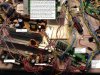
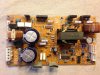
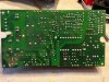
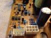
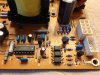
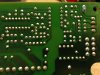
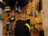
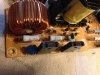
At this point I am not trying to "fool" the PSU to output the 24V but rather trying to figure out the PCB and modify it (with desoldering parts or adding a few) so that the output happens without any kind of feedback (is there a relay that is controlling the output?). This would also allow not to have a 5v supply running on a side all the time. The first picture is the entire set-up when trying to hack it. The rest of the pictures are the closeups of the PSU's PCB. thank you in advance.
 

Attachments

  • PS1.JPG
    PS1.JPG
    592.8 KB · Views: 378
  • PS2.JPG
    PS2.JPG
    576.3 KB · Views: 495
  • PS3.JPG
    PS3.JPG
    499 KB · Views: 409
  • PS4.JPG
    PS4.JPG
    429.3 KB · Views: 541
  • PS5.JPG
    PS5.JPG
    472.5 KB · Views: 357
  • PS6.JPG
    PS6.JPG
    221.5 KB · Views: 320
  • PS7.JPG
    PS7.JPG
    419.3 KB · Views: 323
  • PS8.JPG
    PS8.JPG
    235.7 KB · Views: 326
  • PS9.JPG
    PS9.JPG
    158.6 KB · Views: 321
While I am not familiar with the specific printer, not having the schematic of power supply makes it rather difficult and may not be worth the trouble after all (wow, can't believe your first picture of printer tornado scene):eek:
But if you are up to a challenge, here is a little more info;
Searching the power supply part number comes up with Xerox Phase7700 printer and you can look at it's troubleshooting section which describes the 24V operation dependencies inside the printer( 5v & interlock). With Xerox folks like many others, most everything is FRU (field replaceable unit). No, it does not have any schematic but you can always draw your own---it could be a starting point?
You can get the manual here--(starting at page 117); **broken link removed**

Good Luck.
 
And here' the datasheet for the switching IC M51995AP. You can find application circuits on P16 & P17. It might help you to trace out the circuit for trouble shooting.

Allen
 

Attachments

  • M51995apds.pdf
    507.6 KB · Views: 917
Basically, as others have said, draw the circuit out - otherwise you're just guessing in the dark.

Thanks to the PDF from absf it should be an easy job.
 
Thank you all for the responses. I will start going this route (but will need to discipline myself to stop after 3-4 hours) and post back. I was hoping folks familiar with the PSU designs could help identify the parts that are essential for the DC generation vs. those that are likely used for feedback; but this request could be too naive - not sure.

More to come...
 
OK. I am giving up at this point. According to the manual, there supposed to be feedback loops (for open doors) that must be closed. One of the 5V leads is actually -2v (with thin yellow wire) and I assumed the feedback loop is also based on -2v. There are three yellow wires going into the feedback jack (along with a 5v input) but it would not work does not matter how I tried. Should have paid more attention when taking these apart.

When time allows, I will try to butcher the PSU PCB to see if the feedback can be disabled but, meanwhile, any suggestions to which resistor (I thought it would be a relay) is a culprit will be really appreciated.

thanks.
 
Do not turn on the soldering iron yet.

I would look for what controls the 24V output, what you call "culprit", instead of messing with the design of the PSU itself. Chances are that it is like that by design.

In other words, have you checked what are those 24V applied to and WHEN? Maybe the 24V output is for a certain function only (10A is a lot of power). We can see that the other voltages do not seem to depend of the missing 24V. Your words.

In my case I reversed an EPSON ???850 and just by reading the service manual from A to Z, I was able to use it "as is". By brain surgery I replaced the propietary logic-glue IC plus the micro in charge with a 18F452. Sure, I drawn about 50% of the schematic. The sole available schematic in the Web is a pathetically scanned one, mostly unreadable.

Any chance to compare it with another working printer not disassembled yet? I learnt a lot from the Autotest. Any chance to put it in action (do not forget interlocks) if available?

One word of caution: sensors and interlocks, better you identify them upfront, precisely to avoid them to lock any function that you could need. Eventually that is your problem now.
---------------------------------------------------------------------------------------

Additional comment: Along the time I salvaged components from varied equipment. Lately, I started to keep the PSUs intact. I understand there are more chances that I could use them as they were built than after any tweaking or even their components separately.

Buena suerte.
 
Last edited:
Status
Not open for further replies.

New Articles From Microcontroller Tips

Back
Top