Continue to Site

Welcome to our site!

Electro Tech is an online community (with over 170,000 members) who enjoy talking about and building electronic circuits, projects and gadgets. To participate you need to register. Registration is free. Click here to register now.

  • Welcome to our site! Electro Tech is an online community (with over 170,000 members) who enjoy talking about and building electronic circuits, projects and gadgets. To participate you need to register. Registration is free. Click here to register now.

Retro fit buttons to steering wheel

Status
Not open for further replies.

brear david

New Member
Hi
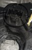
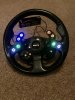
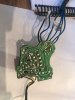
I am about to by a dash 2 lcd display for my pre obd 2 car and would like to control it from buttons on the steering wheel. I’ve looked at several options. Firstly I could buy a set of buttons using wireless control but they are quite expensive and I don’t need to remove the wheel. I thought I could perhaps use the clock spring from a Mazda 3 which has 18 buttons on the wheel, more than enough to control the dash and other things like turn signal, flash, radio etc.
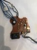
The more I look into it it’s not that simple due to the multiplexing that happens through the can bus of which I don’t have.
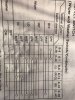
My question therefore is this. Does anyone know of a way I can use a clock spring and adapt my electronics so as to be able to utilise all 18 channels.

Regards

Dave
 
You can multiplex your switches as a 4x5 array. However, this would still require 9 connections. How many conductors are in the clock spring?

If you're able to program a microcontroller then you could have only three wires to carry all the button information.

Mike.
 
The Mazda 3 clockspring appears to have 4 connections:
upload_2018-1-1_6-25-40.png


Yellow is SRS probably. I suspect the 18 buttons are for a serial com or a resistor ladder as is being discussed in another thread here: https://www.electro-tech-online.com/threads/input-and-save-input.152285/

A 2008 F-150 has 4 pins for the SRS and 6 pins for other functions. You might be lucky and find something that fits and has a sufficient number of contacts.

But most likely, if you want a lot of buttons on the steering wheel, you will probably be using a serial com or resistor ladder.
 
Thanks guys for your responses
I thought the connections on the photo were for the airbag and horn and the 8-9 pin connector was for the buttons as in this photo. If so that would make it much simpler.

What do you think?
 

Attachments

  • 7AC474DB-F7E2-4548-812B-D3CD7FEBC6EF.jpeg
    7AC474DB-F7E2-4548-812B-D3CD7FEBC6EF.jpeg
    139.8 KB · Views: 216
Sorry, I missed that in the pictures. For the F150, I had the manuals and didn't need to rely just on pictures.

Do you have the wiring diagram for that clockspring?
 
I wonder if it's a coincidence that a 5x4 matrix requires 9 connections?

Mike.
 
Hi
Just thought I would also mention that I’m actually an aircraft engineer with a bios to the mechanical rather than electronics but having said that I do understand some of the concepts.
I’m more of a “give me a design drawing and I’ll build it” kind of guy Hence I’m relying quite heavily on you guys for help.

Just thought you needed to know before we got too deep and I got lost.

I do remember an 8 channel TDM multiplexer/demultiplexer kit that maplins sold some years ago That would be easy for me or perhaps you would be kind enough to show me how to build one.

If all this is to much to ask I quite understand.

O and thanks for responding on New Years. No hang over then?
 
Thanks for that diagram. It has similarities to the Ford. Namely, it uses a resistor string to "code" several switches with just 2 wires. But given the number of contacts in the connectors, that approach may not be necessary.

One reason I end up buying manuals for my cars is that electrical diagrams I find on the internet frequently are almost impossible to read. Your Mazda one is no exception. Is the link more legible?

It looks like the 6 audio control switches produce a voltage on pins 3(?) and 4 that is proportional to which switch is pressed. It's what is connected to the other pins that I can't decipher. It is possible not all positions are filled.

Are you planning to use just the clockspring or the steering wheel insert too?
 
Best I clarify a bit more.
What I have is a 92 mk2 Toyota mr2 with an after market momo steering wheel which I want to add buttons to. The car has no obd2. I would be fitting several buttons on the wheel and using the clock spring as a means to connect them to the car without the use of a long spiral flex cable as in some old rally cars.
I thought initially that the clock spring had the same connections as buttons hence finding a clock spring from a wheel that had a lot of buttons to give me options. I’m not bothered which clock spring I use just that it will do the job.
Sorry for the confusion
 
When I took a defective clockspring out of my 2000 Honda, it was just a coiled flat flex ribbon cable. Maybe it is just a question of figuring out which pairs of pins connect using an ohmmeter. After that, the assignments could be arbitrary.
 
Hi all
Only a year but I have managed to accomplish what I set out to do and fitted the buttons, rotary switches etc to my steering wheel but I do have a couple of issues upon testing hence my plea for help again.

I used 2 Pololu Pushbutton Power Switches to initiate the turn signals but upon fitting the wheel to my Toyota mr2 mk2 I only get a click and no flasher. Real head scratcher.

Also utilised the wiper circuit board and modified it. But again on fit I have an issue. The wiper when selected is laboured and grinds to a halt when fast speed selected.

The pololu switch diagram is readily available on line and I will attach a couple of picks of the wiper circuit.

Thanks in advance of any help.

Regards

Dave
 

Attachments

  • 2D1103D9-64B1-4561-83B6-D84E73777DD6.jpeg
    2D1103D9-64B1-4561-83B6-D84E73777DD6.jpeg
    1.1 MB · Views: 206
  • 9BEB8E18-B23C-4C2E-ADB2-8BB88D91DAE2.jpeg
    9BEB8E18-B23C-4C2E-ADB2-8BB88D91DAE2.jpeg
    743.7 KB · Views: 203
  • CCA51E7C-C69B-458B-B37A-0F9D8C40A0EB.jpeg
    CCA51E7C-C69B-458B-B37A-0F9D8C40A0EB.jpeg
    176.7 KB · Views: 201
  • 6950D20E-351C-48BA-85E4-8EE970D6870C.jpeg
    6950D20E-351C-48BA-85E4-8EE970D6870C.jpeg
    96.4 KB · Views: 210
First pic is a screen shot of website
Second is how I wired them in
Third is wiper module. I connected all the contacts to a rotory switch
Forth schematic of indicator switches
And lastly pic of wiring diagram for indicators and wash/wipe
 
As per the blurb, the switches don't retain their state when the power input disappears and they usually power up in the 'off' state; so every flash would turn them off when wired as shown.
 
To do what?
 
Status
Not open for further replies.

Latest threads

New Articles From Microcontroller Tips

Back
Top