Continue to Site

Welcome to our site!

Electro Tech is an online community (with over 170,000 members) who enjoy talking about and building electronic circuits, projects and gadgets. To participate you need to register. Registration is free. Click here to register now.

  • Welcome to our site! Electro Tech is an online community (with over 170,000 members) who enjoy talking about and building electronic circuits, projects and gadgets. To participate you need to register. Registration is free. Click here to register now.

Result when 2 sources of emf connected in parallel

Status
Not open for further replies.

Rohan C.

New Member
This is in my theory and so, i guess , is not practical:
2 sources of emf(having negligible internal resistance) are connected in parallel.
(I've attached a rough diagram of the circuit)
What will the current in the circuit be?
 

Attachments

  • circuit.JPG
    circuit.JPG
    5.1 KB · Views: 437
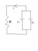
If E1 and E2 have the same value, E, then the current in R will be E/R.

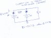
IF E1 and E2 don't have the same value, then the effective voltage applied to R will depend on the resistance of the wires connecting E1 and E2 together.

In the real world, the wires connecting E1 and E2 would probably be copper wires of fairly low resistance, so that if E1 and E2 were of differing voltages, a large current could flow in those wires. Depending on just how much current E1 and E2 could supply, the connecting wires could suffer effects ranging from just getting a little warm, to melting the wires. Damage to the voltage sources might occur.

Not a good thing.
 
It would be the same as making a short-circuit across a battery of a lower voltage. The two original batteries would try to cancel out each other's voltage, but since they were not equal voltage there would be leftover voltage. This leftover voltage is the equivelant battery of lower voltage. This short-circuit would make the two batteries completely ignore the resistance in the circuit and no current would flow through it.

Another way to think about it (and more physically accurate) is that the higher voltage battery would try to charge the lower voltage battery through a resistance of zero ohms (or whatever the resistance the wire is between the two batteries). That means a short-circuit since you are producing a voltage difference across a very very low resistance.
 
Last edited:
The Electrician:
What i want to know is how you got the resultant emf to be equal to E if they both had the same value?
 
Last edited:
An analogy would be using a second car/vehicle battery to jump start a vehicle with a 'low' battery.

The higher voltage battery would act as a charging current source into the lower voltage battery, until both batteries were at the same voltage.
 
The Electrician:
What i want to know is how you got the resultant emf to be equal to E if they both had the same value?
It's just a basic rule of electronics: Things (whether it be groups of components or just single components) in parallel have the same voltage across them. If two things share the same two connection points, they have the same voltage because the voltage between those two connection points can't be multiple voltages at the same time. For future reference, a "connection point" is actually called a node.

Having two different voltages in parallel will try to drive enough current through the resistance in series with each voltage source (that is not shared with the other resistance) to make it so the two source-resistor combinations in parallel have the same voltage.
 
Last edited:
What they said. Here is a practical way to parallel non-ideal voltage sources"
 

Attachments

  • parallel.jpg
    parallel.jpg
    105.2 KB · Views: 331
Status
Not open for further replies.

Latest threads

New Articles From Microcontroller Tips

Back
Top