Continue to Site

Welcome to our site!

Electro Tech is an online community (with over 170,000 members) who enjoy talking about and building electronic circuits, projects and gadgets. To participate you need to register. Registration is free. Click here to register now.

  • Welcome to our site! Electro Tech is an online community (with over 170,000 members) who enjoy talking about and building electronic circuits, projects and gadgets. To participate you need to register. Registration is free. Click here to register now.

Resistor value

Status
Not open for further replies.

Mick5370

New Member
Hi, I have a pcb from a 3 way fridge that runs on 230vac, 12vdc and gas. Fridge works on the 12vdc from alternator and gas but not on the 230vac mains supply. The pcb components have been encased in resin however there was a large scorch mark on the resin and I have dug out the resin to reveal a resistor that has blown. The identifying bands are all but unreadable so I am trying to work out what the resistor value should be. The mains supply powers a 230vac - 220 watt heating element so I calculate this to be just below 1 amp. The rating plate on the pcb states 230vav - 2.5 amp so I calculate that I would need a 240ohm 1/2 watt resistor. The pcb is no longer available as a replacement and a new fridge would cost £1200 to replace so I would really appreciate any assistance because it seems such a waste to dispose of a perfectly good appliance for the sake of a resistor. I have attached some images of the pcb and existing resistor to try and illustrate. Many thanks for any help
 

Attachments

  • 20200708_181548.jpg
    20200708_181548.jpg
    1.3 MB · Views: 184
  • 20200708_172821.jpg
    20200708_172821.jpg
    380.6 KB · Views: 179
I don't know how you worked out that the resistor would need to be 240 Ohm, 1/2 W. A 240 Ohm resistor will produce 1/2 W when there is around 11 V across it and 45 mA flowing through it. The heating element will be around 240 Ohms, but it is rated at 220 W so it is a much larger size than the blown resistor, and it won't be on the circuit board.

A lot more information is needed about this if anybody can help. A photo of more of the circuit would help. Is there anything visible on the back? Where do the wires go?

Does the fridge have a temperature controller when running on 230 V? I know that some of those fridges have more powerful cooling on 230 V than on 12 V.

There's a relay on the circuit board. It's coil voltage is 12 V dc, and it looks as though the contacts have got hot and damaged the case of the relay.

That 12 V relay could be run from the 12 V input, so that it is off when the 12 V input isn't there. However, my best guess is that the relay is run from the 230 V supply with a transformerless supply, and that the square component between the relay and the resistor is a bridge rectifier. In that case the burned resistor may have been part of that transformerless supply, as many of those have components that run very hot. However, the burned component can't be a simple resistor to run that relay from the mains as it would be far too small to have the power rating required.
 
Hi, I have a pcb from a 3 way fridge that runs on 230vac, 12vdc and gas. Fridge works on the 12vdc from alternator and gas but not on the 230vac mains supply. The pcb components have been encased in resin however there was a large scorch mark on the resin and I have dug out the resin to reveal a resistor that has blown. The identifying bands are all but unreadable so I am trying to work out what the resistor value should be. The mains supply powers a 230vac - 220 watt heating element so I calculate this to be just below 1 amp. The rating plate on the pcb states 230vav - 2.5 amp so I calculate that I would need a 240ohm 1/2 watt resistor. The pcb is no longer available as a replacement and a new fridge would cost £1200 to replace so I would really appreciate any assistance because it seems such a waste to dispose of a perfectly good appliance for the sake of a resistor. I have attached some images of the pcb and existing resistor to try and illustrate. Many thanks for any help

I would suggest it's almost certainly NOT just the resistor, it's much likely just a symptom of the faulty power supply, not the cause, and has blown as a protective measure due to failure elsewhere in the PSU.
 
Thank you Diver300, I think that your best guess is correct that the relay is powered by the 230vac. I have managed to find a wiring diagram of the pcb and have taken some pictures of the control panel fascia and reverse. I'm no electronics expert, I was basing the 1/2 watt resistor on the physical size of the blown resistor in the pcb and the 240 ohm on getting 1amp at 230v. Again, any help would be greatly appreciated. I have been trying to fix this problem for 3 years. I'm determined to not waste a good appliance.
Thanks Michael
 

Attachments

  • Screenshot_20200711-185524_Chrome.jpg
    Screenshot_20200711-185524_Chrome.jpg
    386.9 KB · Views: 152
  • 20200711_144350.jpg
    20200711_144350.jpg
    694.1 KB · Views: 142
  • 20200711_144335.jpg
    20200711_144335.jpg
    1.2 MB · Views: 153
  • 20200711_184529.jpg
    20200711_184529.jpg
    1.1 MB · Views: 164
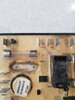
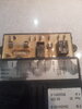
Now that you've shown a bit more of the circuit board, I can see that it's encased in a black plastic box so that the back won't be visible.

The heating element, K in the diagram, will be around 240 Ohms. The circuit board will switch it on and off depending on the temperature. The wiring to the heating element will have much less resistance, as it shouldn't get hot.

If your fridge works fine on gas and 12 V, my suggestion would be to put the mains directly onto the mains heating element. To maintain the temperature control, you would need to fiddle a few things, so here is what I think you would need to do:-

1) Find a 230 Vac input 12 V power supply. It won't need to be a high rating, and 1 A will be plenty. You've probably got a few from old routers etc. Connect that so that it is powered by the mains input. A power supply with a wired input or a C8 input might be more convenient to wire up than a wall wart.
2) Connect a change-over relay so that the 12 V of the fridge is powered from the power supply when the power supply output works, and from the normal 12 V feed when the power supply doesn't work. (You can use an automotive change-over relay for that. Wire the negative of the power supply to the negative of the normal 12 V feed and to pin 85 of the relay. The normal supply goes to pin 87A and the output of the 12 V power supply goes to both pins 86 and 87. The 12 V input of the fridge is powered from pin 30. You need heavy-duty wire for the normal supply and the connection to pin 30)
3) Connect another change-over relay so that the fridge's 12 V heater can't work if the mains is on. (You can do that with a second change-over relay. Pins 85 and 86 are connected as the first one. Disconnect the wire from pin 87 of relay "O" on the diagram and connect that to pin 87A on the second change-over relay. Connect pin 30 of the second change-over relay to pin 87 of relay "O", also with heavy wire. Do not connect anything to terminal 87 of the second change-over relay)
4). Get the fridge circuit board to control the 230 V heater. Find a normally open relay, 12 V dc coil, mains rated contacts, so you can't use an automotive relay for that. The contacts only needs to be rated to 2A or so. One like the relay in you first photo would be fine. Connect the coil in parallel with the coil of relay "O". Wire the the live mains input through the contacts of the relay to one side of the 230 V heater and connect the other side of the heater to neutral.

Do not connect the mains, live or neutral, to the fridge electronics.

The plan is that the fridge electronics will run from 12 V, and behave like it is on 12 V, when in fact the heater is running on 230 V ac. When 230 V ac is connected, the fridge electronics will be powered from the power supply. The 12 V heater will be disconnected to stop it overloading the power supply. When the fridge electronics turns on the 12 V relay to power the 12 V heater, the relay for the 230 v heater will turn on, so the 230 V heater will run.

When the mains is disconnected, the fridge electronics works as normal. If it runs on 12 V, the relay for the 230 v heater will turn on as well, but it will have no effect because the mains is disconnected.

The plan won't work well if the fridge electronics has a very different strategy on 12 V that is has on 230 V ac.

I assume the mains input will be fused at 3 A or less. The plug fuse will be fine for that.

There is a lot there that can go wrong, so draw it out, and post the drawing here if you at all unsure. Be very careful fault-finding with any 230 V stuff. What I have suggested minimises the mains wiring and all the relays will have 12 V coils. The heater wiring for the 230 V stuff must be properly insulated and kept clear of everything else. The heater wiring for the 12 V stuff must make good connection as it is high current.
 
Hello Diver300
Thank you so much for taking the time to help me solve this problem. I really can't believe that you and everyone on this forum give such qualified advice for free. I'm a beginner with electronics and although I kind of understand your instructions, I wouldn't be confident in executing them. I might cause more damage than already exists. I thought that it might just be a case of fitting a resistor. Again, thank you very, very much for your help. Would you know of anywhere that I could send it to for repair or assemble the components as you have detailed? Or could I pay yourself to have a look at it?
 
Status
Not open for further replies.

Latest threads

New Articles From Microcontroller Tips

Back
Top