Continue to Site

Welcome to our site!

Electro Tech is an online community (with over 170,000 members) who enjoy talking about and building electronic circuits, projects and gadgets. To participate you need to register. Registration is free. Click here to register now.

  • Welcome to our site! Electro Tech is an online community (with over 170,000 members) who enjoy talking about and building electronic circuits, projects and gadgets. To participate you need to register. Registration is free. Click here to register now.

Resistor Selection Virtual Ground Circuit

Status
Not open for further replies.

pnielsen

Member
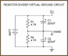
I would like to use this simple voltage splitter circuit. Yes, I am aware of its limitations.

In the configuration shown, how is the value and wattage of the two identical resistors calculated in relation to the input voltage and output current?

In my current application, there is 12VDC in and a total draw of 1A.
 

Attachments

  • virtual_ground_circuit.png
    virtual_ground_circuit.png
    2.6 KB · Views: 225
Yes, I am aware of its limitations.
Are you?

If the 1A is going through the virtual ground and you want, say no more than a 100mV drop due to that current, then the equivalent resistance of the voltage divider can be no greater than 0.1/1 = 0.1Ω.
This means resistor R1 and R2 would be 0.2Ω each and each resistor would dissipate 6²/0.2 = 180W. :eek:
 
I am wondering if this bears out in practice. I did once build a similar circuit using a pair of 10R 5W resistors and 1000uF caps. It split 24VDC into two 12VDC rails from which I drew about 10W audio (not hi-fi obviously). Each rail powered a separate amp. The resistors ran warm but not hot. All looked good on the scope.

The purpose of my OP was to understand how the R values are properly chosen. Now you have me mathematically worried.
 
The divider only has to handle the net difference in the load currents. If the load currents are almost equal, then the resistors can be higher. Trouble happens if the load currents are highly asymmetrical.
 
What is generating this 1A of load?
 
In the practical example I gave above, the loads were two air coils. Each was driven from a separate NPN and PNP emitter follower. Since the signals were DC shifted but still in-phase, the drawn currents would be "symmetrical". I imagine it would be a differnt story if the outputs had been anti-phase.

Retruning to my orignal question. Are there any articulable guidelines for choosing the resistor value, or do I just sniff for smoke?
 
Are there any articulable guidelines for choosing the resistor value, or do I just sniff for smoke?
Sniffing for smoke is the last step. :rolleyes:

It depends upon the current going through the virtual ground back to the power supply and the amount of voltage drop you can tolerate from that current.

Any load current going to the virtual ground will need to go through the virtual ground resistors.
So the engineering decision is how much virtual ground voltage drop can be tolerated due to the virtual ground current (which will subtract from the load voltage). That voltage value depends upon the system/circuit requirements.

Next you calculate the equivalent virtual ground resistance from this virtual ground current for the tolerated ground drop: (Vdrop/Ignd) = Req.

Then you use two equal value resistors of resistance (2*Req) for the virtual ground divider circuit.
The power dissipated by the resistors due to the power supply voltage determines the required resistor power rating (which should be derated to about twice the calculated value).

Now you power it up and sniff for smoke.
 
Thank you for that clear explanation. You mention that "Any load current going to the virtual ground will need to go through the virtual ground resistors".

But what happens if the circuit is also driving a resistive load? For example, if I there are two 10R resistors on the splitter and a transistor on each rail is symmetrically driving a 10R resistive load to VGND? Is the current then shared equally between the splitter and powered load?

If so, I would want to increase the value of the spliiter resistors. In a bench situation, e.g. viewed on a scope, what would be the observable effect of having increased them too much? IOW how would the output be degraded?
 
Is this what you were asking about?
R1 and R2 are the splitter resistors. R3 and R4 are the loads. R3 varies from 5Ω to 15Ω (x-axis of the plots). V(vp) shows what happens to Vp while V(vn) shows what happens to Vn. Note that Vp-Vn is exactly 20V (V1).

The blue and violet plots show the power dissipation in R1 and R2 respectively as R3 varies.
Notice the outputs are truely split only when R3 = R4 = 10Ω. (Note that R1=R2=10Ω, not 4700Ω like in your original posting)

77.png

Regulation is piss poor. Power lost in R1 and R2 is very high; all in all a terrible way to split a power supply.
 
Last edited:
Thanks. That plot illustrates the problem very well.

I suppose the next step up from resistors and caps is as per this uploaded diagram with a high power op amp like an LM675 to deliver the 1A required.
 

Attachments

  • vfb-opa.png
    vfb-opa.png
    3.3 KB · Views: 160
If the signal is AC, you can bypass the virtual ground resistors with capacitors to allow higher resistor values.
Obviously the capacitors must be large enough to have an impedance significantly less than the load resistance at the minimum signal frequency.
 
I would have thought the VG resistors are already "bypassed" by the large filter cap wired in parallel with each.

Could you please provide a specific example of how to apply what you have described? Let's say for a 12VDC supply split into 6VDC rails powering a 12W load at low audio frequencies.
 
Why do you need a high power virtual ground? Do you feed plus and minus DC to something?
I made many AC opamp and power amp circuits with ICs that need a positive and negative supply but I used a single positive supply and biased the opamp inputs at half the supply voltage. The inputs that are biased use a tiny current of only 0.1uA for an oPA2134 opamp or 0.2nA for a TL072. Then the bias resistors are usually 100k ohms. The input and output have coupling capacitors. If there is a negative feedback resistor to ground then it has a series capacitor.
 
I would have thought the VG resistors are already "bypassed" by the large filter cap wired in parallel with each.

Could you please provide a specific example of how to apply what you have described? Let's say for a 12VDC supply split into 6VDC rails powering a 12W load at low audio frequencies.
Are you familiar with the impedance of a capacitor as a function of frequency?
Your circuit has 220μF decoupling caps.
At 20Hz the capacitor impedance 1/(2pi*20*220μ) = 36 ohms.
Thus 1A of current will drop 36V across the cap.

If you wanted to reduce that voltage drop to 100mV (0.1Ω), that would require a capacitor of 1/(2pi*20*0.1) = 796mF or 796,000μF.
 
A rule of thumb is that the current unbalance between the two loads, must be significantly less than the current thru the virtual ground resistors. Let's say, one third, for simplicity's sake.

Let's say you have 100 mA unbalance. Then you would choose a current thru the virtual ground setting resistors of at least 300 mA. With a 12v supply this means 20 + 20 ohms each resistor.
 
Let's say you have 100 mA unbalance. Then you would choose a current thru the virtual ground setting resistors of at least 300 mA. With a 12v supply this means 20 + 20 ohms each resistor.
As long as you can tolerate a 1V shift in the ground voltage by the 100mA going through the 10Ω equivalent resistance of the virtual ground resistors.
 
Exactly, that is why I assumed for simplicity's sake, only 1/3 of the current.

If one requires a smaller voltage shift, the resistors will become so small, and the current wasted thru them so large, that the limitations of such a simple circuit become painfully evident.
 
Thanks for all the helpful input. Understanding the situation better, I have decided to use this circuit, minus the caps and filtering since the application is not that critical.

Do I assume correctly that less current will be lost with the op amp splitter than if I just use resistors and caps alone as in my OP?

Can this difference be quantified?
 

Attachments

  • l165_dual_supply.png
    l165_dual_supply.png
    133 KB · Views: 148
Do I assume correctly that less current will be lost with the op amp splitter than if I just use resistors and caps alone as in my OP?

Can this difference be quantified?
Yes, the current will likely be less with the op amp.
The difference is the current through the resistors versus the current required by the op amp (from the spec sheet) plus the current through R1 and R2 in the op amp circuit.
 
Status
Not open for further replies.

Latest threads

New Articles From Microcontroller Tips

Back
Top