Continue to Site

Welcome to our site!

Electro Tech is an online community (with over 170,000 members) who enjoy talking about and building electronic circuits, projects and gadgets. To participate you need to register. Registration is free. Click here to register now.

  • Welcome to our site! Electro Tech is an online community (with over 170,000 members) who enjoy talking about and building electronic circuits, projects and gadgets. To participate you need to register. Registration is free. Click here to register now.

Resistance sensor help...please :)

Status
Not open for further replies.

Adam4444

New Member
I bought this liquid level sensor to pump down liquid in a brewery for automation. However, there are a lot more connections than I anticipated and I do not want to fry the board. Can anyone help me understand these schematics? Every time I call the company no one answers. Any help would be super.
 

Attachments

  • 20170909_143227.jpg
    20170909_143227.jpg
    1.6 MB · Views: 128
  • Models-NS127-NS128-and-NS143-Dual-Probe (1).pdf
    1.5 MB · Views: 131
Almost forgot...I am running 110v not 220. What's throwing me off is that there are two fast-on connectors for each connection....even the connections to the probe wires.
 
I am running 110v not 220.
I am assuming you are using a part with "-240" in the part number.
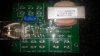
It looks to me that L1, L2 is where you connect power to power the brains. 220 in your case. So Line red and Line white.
L= low probe, H = high probes, C = tank ground or very low probe.

There is a pump up and a pump down version.

NO = normal open, NC = normal closed, COM = common. So the relay is a switch that connects COM and NC, and when energized it connects COM and NO. There will never be a connection from NC to NO.

They show the power connected to NO and NC. The pump on COM and NO.

I would connect Line 1 and Line 2 to L1 and L2.
Then connect L1 to NO and L2 to NC. (or the reverse of that) Assuming the 220V is the same for the pump and the brains.
Now connect the pump (load) to COM and NO.

Is that what you see?
------------------edited------
COM for the probes and COM for the relay are not the same thing!!!! Do not connect them together.
 
Thanks for the input Ron. I am running 110 not 220. Should I run hot to L1 and neutral to L2? Are the connectors just behind L1 and L2 there to connect over to NO and NC? If so, that would mean hot to NO and neutral to NC.
 
Thanks for the input Ron. I am running 110 not 220. Should I run hot to L1 and neutral to L2? Are the connectors just behind L1 and L2 there to connect over to NO and NC? If so, that would mean hot to NO and neutral to NC.
L1 and L2 are just names. There should not be a problem if L1 is Nuetral or Hot.

I think the "connects behind" are connected to the ones in front. So I would use the behind connections to jump over to NO and NC.
 
So I ran the wiring hot to L1, the jumped hot to N.O. Then neutral (common) to L2, then jumped that to the COM connector. Then ran the N.O. output to the hot side of a 110 outlet that pump plugs into. Then ran the COM output to the other side of the outlet, where you traditionally run the nuetral. When powered on without the top wire in solution, the outlet shows as energized N.C. which shouldn't be until the top wire is in solution. When I put the top wire in solution, the breaker trips. The low probe wire is not contacting the steel vessel, just solution, and the COM on the probe is connected to the vessel. What am I doing wrong? Photo of wiring attached
 
Ron I just reread your guidance and realized I had L2 going to COM. Switched that over to NC and no more breaker trips. However, the outlet now shows energized until top wire hits solution. The sensor then switches it off, or N.O. I want it to go from N.O. when the top wire is not in solution and then switch to N.C. or energized, when the top wire is in solution. That would then activate the pump to pump down. Thank you so much for your help this far!!!
 
You do not need a link to the NC contact. I am assuming that L1 is what we call live in the UK and L2 is what we call neutral. (Which is nominaly at earth potential.)
So connect the incomming L1 to terminal L1 and the incomming L2 to terminal L2. Link L1 to the NO contact. Connect one wire to the pump to the common terminal. connect the other wire from the pump to terminal L2. Ron will correct this if have got the L1 L2 to ourlive an neutral the wrong way round. It would still work but it nod good practice to switch what we call neutral as it would leave the motor live when the relay was open.

Les.
 
Status
Not open for further replies.

Latest threads

New Articles From Microcontroller Tips

Back
Top