Continue to Site

Welcome to our site!

Electro Tech is an online community (with over 170,000 members) who enjoy talking about and building electronic circuits, projects and gadgets. To participate you need to register. Registration is free. Click here to register now.

  • Welcome to our site! Electro Tech is an online community (with over 170,000 members) who enjoy talking about and building electronic circuits, projects and gadgets. To participate you need to register. Registration is free. Click here to register now.

replacing flasher relay with 555 timer

Status
Not open for further replies.
Yep, I'm back with more 555 madness..

I have a mercades 113 pagoda with a failed flasher can unit due for MOT first thing in the morning.. I pretty sure I can swap it for a 555 circuit until the replacement relay arrives, but I've no idea how.

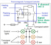
Here's the best relay schematic I could find
b3wcm4C.jpg


While I was looking at the actual thing earlier I couldn't make sense of it, now I've seen the schematic I'm even more confused.

49 is a permanent live, 49a is also live and feeds the lights when switched then heating element trips 31, which brakes the live, heating element cools, cycle begins again?? Meh, the mechanical aspect of it throws me off I guess.

Anyway.. can anyone see how I can set up a 555 timer for this? I've got several flashing circuit diagrams to work from but they don't seem to suit the task, it looks like there's a permanent live in and a permanent live out, and when the column stork is switched the the live out goes through the load to ground and triggers the flash on/off switch.. so I think I need to have a circuit with a Vin and Vout then a timed signal when Vout is grounded? Non of my flasher cuircuit diagrams have that.
Appreciate any help. Thanks
 
sh¡t - it's an automobile - i thought it's a water heating system (damnit - silly me :arghh:)
basically while the circuit is closed your relay interrupts by thermo spring (cools/engages when lamps OFF ~ heats/breaks when lamps ON)
i guess the ↑schematic↑ is bullsh¡t . . . on a second scan its a resistor (lower current than the lamps) so ◄◄ (heats/engages "control" when lamps ON ~ cools/breaks "control" when lamps OFF)

there's a circuit
there are actually **broken link removed** ... many circuits
 
Last edited:
Hey Nigel.
Thanks for the swift reply. I have a diagram not too dissimilar to that one, but yeah, interfacing that with the three wires I currently have dangling down is a bit of a stretch. A plug 'n' play type deal would be the ideal. If you find yourself perusing your old book before tomorrow.. ;):angelic:

Hey Ci139.
Yeah, it's a classic car. There's hundreds of timer circuits for sure.. but I'll need help isolating the particular one I need in the next few hours though :nailbiting:
 
need in the next few hours
hmm

. . . attach stright to fuse blink by hand (according to schematic witch i doubt - 4A going through there)

otherwise if the lights sit on a separate relays L/R you need a better schematic - ? fast 2h ago , muhahaa
 
Last edited:
Blink by hand, ROFL.

Been looking at the cars wiring diagram and I'm 99% sure I've misunderstood the flasher relay diagram. A typical 555 flasher cuircuit should work thankfully, my only concearn is I'll need around an 8amp bjt or mosfet for the high side so the output pulse from the 555 needs to present the base or gate with a negative.. all my flasher schematics are positive outputs :meh: Pretty sure I can work it out in time though :)

Thanks for your help guys!
 
Last edited:
Perhaps i'm thinking too complex but i can't get it better at 2AM
(didn't got better by the evening - a very raw concept - but it seems to do what's required :eek:)
 

Attachments

  • K554CA3-plus.west_SiSo_10X.png
    K554CA3-plus.west_SiSo_10X.png
    50.5 KB · Views: 281
  • K554CA3-plus.west_SiSo_12X.png
    K554CA3-plus.west_SiSo_12X.png
    70.6 KB · Views: 277
Last edited:
One of those pull switch types? Those contain the park, turn signal cross circuit, and the emergency flash on.... the fourth pull click? The lever for the turn signals complete by closing contacts and as mentioned to heat a bimetal turn signal relay element that when heated opens, breaks contact with bulbs, cools then closes again to re light the bulbs. The turn lever brakes the connection ultimately.

Turn signal is possible as the 555 timer in this quick fix would be in a slow pulsing mode at all times.

Thoughts are if the 4 way emergency also uses the same relay for all lights to flash, this would work IF the control switch functions that way (uses the same relay for both turn and emergency).

The 555 timer would pulse at a low on, off, and the timer would function a P-Channel (to drive the lamps as they are often chassis grounded at their location for reduced production cost) to power the lamps dictated (control) determining what row, left/right to be linked via the turn signal lever.

.... The Timer should be left ON, IF the 4 way emergencies are tied into the same relay and are not working as well, why? If the ignition switch is off and the timer would be off as well, the emergency would not work with the ignition off if you wanted the ignition switch to control the 555 timers power. The emergency would tie the P-channel to all lamps at activation of Emergency switch. (Running the 555 timer at all times may beBad for battery if left on for a long period, don't know the battery, tho this is a quick fix, temporary) ?
: Edited the bad for battery remark :
----------------------------------
So 555 Timer slow constant pulsing set by the time you want (looks authentic OE blinking) , a P-Channel that can carry the total lamp current (all) with some current head room left for transistor to drive the lamps, or parallel transistor arrangement, P-Channel driving the to the lamps connector from the relays port, and the main turn signal lever controlling left or right as usual. BJT, current Base to switch on/ documentation, FET, follow documentation of that part for Gate voltage. This is a likely sourcing operation of power to the lamps.
----------------------------------

The other relays port should have a constant power regardless, I'm assuming a 2 pin relay with a positive supply from battery? Careful, those relay ports for the flasher lamps may not be fused from the battery to work in event of vehicle damage unless the battery is defunct. (not likely)
 
Last edited:
Should work. Direct drive to the signal lever via the 1 of 2 primary pin contacts. The Control is not needed as that enables/disables the entire relay somewhere else.

:Edit: my bad on the late image posting....Others here. Bothersome. I should set my .45 down on the table more often.... So quiet now.... :)
 

Attachments

  • BlinkRL.png
    BlinkRL.png
    80.9 KB · Views: 267
You can do it with a relay and a few components.

Flasher-simple.gif

This simple circuit flashes a globe at a rate according to the value of the 180R and 2200u electrolytic.
 
How simple to forget the simple things. That could be a replacement for an OE config relay being it's a classic car. The OE parts are bound to be a bit much and the methods used in design a bit original or replicated possibly being a bit problematic to acquire at some point.

The single power line feeds the relay armature and coil through the 180 Ohm in to the capacitor, the signal lever activation sinks the capacitor functioning the relay to switch on changing the caps state holding the relay on for a time.

Over all using 2 ports, the power positive and the lamps ports only.

Would the ESR of the capacitor need be in a moderate range?
 
Got it sorted, nice and simple too.. for a change.

Just thought I'd upload a pic of the offending relay, it reminded me of looking into the back of a valve radio as a child :rolleyes:
0bgckjC.jpg


Steampunk-tastic.. I'm keeping it :D
 
i wonder the guy who sees this mess as a product - the guy who "designs" these - not that it wouldn't be ingenious - but there is such on a market in post space age - and again the designer accepts such as a final complete product (though the transistors wouldn't look much better at close up) . . . find the product safety features built in to that design -- seriously (it shouldn't set on fire nor stay alive for it's case to reach high temperatures ... or is it external fuse only ??)
 
It's from an early 1960's car still using 1950's or earlier technology. The relay (or electronic magnetic thermal switch controller lol) is fused and housed in an aluminium cannister. They're actually pretty reliable, many of the 113's I've worked on still have the original flasher can 50 years on!
 
i quite can't yet make the 555 only v. of it
 

Attachments

  • K554CA3-plus.west_SiSo_13X-h.png
    K554CA3-plus.west_SiSo_13X-h.png
    49.1 KB · Views: 272
  • K554CA3-plus.west_SiSo_13X-hs.png
    K554CA3-plus.west_SiSo_13X-hs.png
    49.3 KB · Views: 254
  • K554CA3-plus.west_SiSo_13X-hss.png
    K554CA3-plus.west_SiSo_13X-hss.png
    43.6 KB · Views: 255
  • K554CA3-plus.west_SiSo_13X-a.png
    K554CA3-plus.west_SiSo_13X-a.png
    50.9 KB · Views: 249
Status
Not open for further replies.

Latest threads

New Articles From Microcontroller Tips

Back
Top