Continue to Site

Welcome to our site!

Electro Tech is an online community (with over 170,000 members) who enjoy talking about and building electronic circuits, projects and gadgets. To participate you need to register. Registration is free. Click here to register now.

  • Welcome to our site! Electro Tech is an online community (with over 170,000 members) who enjoy talking about and building electronic circuits, projects and gadgets. To participate you need to register. Registration is free. Click here to register now.

Replacing a ceiling fan pull switch

Status
Not open for further replies.

ElectroGeeza

New Member
Hey all!

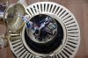
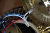
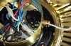
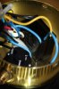
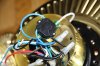
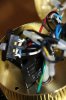
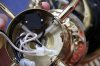
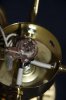
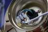
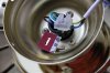
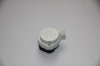
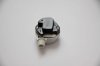
I need to repair a ceiling fan. It is a combined 5 bulb light fixture with a 3 speed fan. There is one pull switch for the light and one for the fan. The string coming out of the pull switch for the fan went off. It went off inside the switch so the whole switch needs to be replaced.

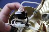
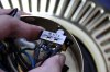
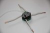
I found a pull switch which is pretty much identical to the original. The only problem is I had a friend of mine look at this problem and when he removed the broken pull switch, he failed to take note of which wires go to which holes on the switch. So now I don't know how to install/wire it. Maybe you can help?...

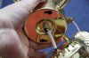
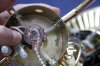
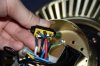
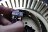
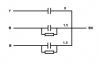
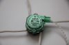
The switch has 4 connectors on it. They are labeled as 1, 2, 3, and L.

I will submit pictures and probably try to make some kind of diagram of the wiring.

Thanks in advance!
 
Here are a few pictures of the whole thing. You can see the pull switch on one of the pictures (IMG_2781.jpg) here, it's that green looking thing.

Can someone tell me what that big black thing is?... is that the component responsible for changing the speed of the fan?

I can upload more pictures if needed. But right now I will try to make a diagram of the wiring.
 

Attachments

  • IMG_2781.JPG
    IMG_2781.JPG
    239.4 KB · Views: 38,362
  • IMG_2782.JPG
    IMG_2782.JPG
    124.4 KB · Views: 7,881
  • IMG_2761.JPG
    IMG_2761.JPG
    270.8 KB · Views: 13,393
  • IMG_2784.JPG
    IMG_2784.JPG
    182.5 KB · Views: 5,727
  • IMG_2793.JPG
    IMG_2793.JPG
    213.6 KB · Views: 7,649
  • IMG_2794.JPG
    IMG_2794.JPG
    179.8 KB · Views: 5,019
  • IMG_3578.JPG
    IMG_3578.JPG
    198.5 KB · Views: 5,161
  • IMG_3580.JPG
    IMG_3580.JPG
    225.3 KB · Views: 4,815
  • IMG_3582.JPG
    IMG_3582.JPG
    213 KB · Views: 6,232
  • IMG_3591.JPG
    IMG_3591.JPG
    160.3 KB · Views: 3,802
  • IMG_3587.JPG
    IMG_3587.JPG
    193.5 KB · Views: 4,707
  • IMG_3586.JPG
    IMG_3586.JPG
    194.3 KB · Views: 11,745
  • IMG_3597.JPG
    IMG_3597.JPG
    180 KB · Views: 5,556
  • IMG_3600.JPG
    IMG_3600.JPG
    163.6 KB · Views: 4,300
  • IMG_3604.JPG
    IMG_3604.JPG
    191.3 KB · Views: 4,894
  • IMG_3611.JPG
    IMG_3611.JPG
    206.4 KB · Views: 3,885
  • IMG_3612.JPG
    IMG_3612.JPG
    204.3 KB · Views: 4,833
Last edited:
This link may help. The large black thing should be a capacitor. The worst thing anyone can do with one of these is not mark the wires during disassembly because the fans use so many variations of wiring.

For many four wire pullchains:

L - Black, 1 - Grey, 2 - Brown, 3 - Purple
L - Orange, 1 - Black, 2 - Yellow, 3 - Purple
L - Black, 1 - Grey, 2 - Brown, 3 - Green
L - Grey, 1 - Yellow, 2 - Purple, 3 - Black
L - White, 1- Black, 2 - Blue, 3 - Yellow

The above color scheme was taken from this link. That may help also. You may also get lucky with a Google of the fan name and model number.

Ron
 
Use a meter to find who's the power feed, the others are the different speeds.
Clip the feed to each of others to find their speed.
Then:
Feed is L(line), 1 is slow, 2 is medium & 3 is fast (my S/M/F order preference)

P.S. review quality of "friends" help. G.H. <<<)))
 
This is by far the best/only set of possible diagrams that I have found on the web: https://www.hurontel.on.ca/~taitg/pages/cfan.html

There are SO many different switches used in a ceiling fan, so in hindsight I would have reccomended starting here: www.ceilingfanparts.com for a replacement switch.

The number of wires on the black thing (capacitor) and the markings e.g. 1 uf (blue), 3 uf (black), green (common) would be a big help.

In the MAJORITY of cases, you may find a 3 wire capacitor and 3 speeds. On the lowest speed, the lowest value of capacitor is selected. On the highest (in this example) blue and black would be shorted together giving the highest value of capacitance for the highest speed.

With labels as 1,2 3 and L anything is possible. What the capacitor is labeled is key. Is it 4 speed or 3?

FWIW: Capacitors in parallel add and the highest value capacitor is the highest speed. Capacitors in series follow the 1/Ct = 1/C1+1/C2...1/Cn rule. There could be one capacitor and winding selects or the switch could select various combinations of the capacitors.
 
Last edited:
Thanks guys!

I found this tip on Fixya:

There is a common wire, usually the black one. You can easily test this by using the continuity setting on a multi meter. The common wire will create a connected circuit to each of the other three wires (if the black wire doesn't work, it is possible one of the other wires is the common--you may have to try more than one).

Link: **broken link removed**

But I was unable to find a common wire as described, i.e. one that will cause the buzzer to go on (i.e. less than 30 Ohm) when connected to one of the three other wires. But I did find one that causes the buzzer to go on when I probe between that wire and a wire on the incoming power connection. It is brown in color which usually indicates incoming power line or lead (L). Is this wire supplying power to the fan?...

I have made a simple diagram of the wiring, as you can see in the attachment. It's divided into 3 "decks". The power lines go to the "motor deck" first, from where some of the wires connect to the motor and branch out to the the "capacitor deck" while others just pass through the motor deck - through the motor shaft actually. Then there are wires branching out from the capacitor deck to the "light deck". Take a look at the attachment.

What do you make of this?...

The fan pull switch wiring you see in the diagram is the one I tried last time, but that didn't work. I have marked it with question marks.
 

Attachments

  • Diagram4.png
    Diagram4.png
    112.7 KB · Views: 3,801
Last edited:
A yellow and the brown don't look right.

Can you write down what is on the capacitor. Need to see the caps and values. e.g. ------| |------
3uf
and the colors.

And if possible, the resistances of the motor windings. It might be tough to do.
 
Last edited:
A yellow and the brown don't look right.

Can you write down what is on the capacitor. Need to see the caps and values. e.g. ------| |------
3uf
and the colors.

And if possible, the resistances of the motor windings. It might be tough to do.

You mean something like this?...
Code:
             9
Y ------||-------|
             1.5 |
B ------||------------- BK
      |_---_|    |
        ---      |
             1.5 |
B ------||--------
      |_---_|
        ---

Because that's what it says on the capacitor package. You can see it on one of the attached pictures above.

The colors coming from the capacitor are Black, Black, Blue, Blue, Yellow. According to the capacitor schematic they are connected like this:

BK = Black + Black
B = Blue
B = Blue
Y = Yellow

Do I need to disassemble the motor to properly measure the resistance of the motor windings?...
 

Attachments

  • Diagram5.png
    Diagram5.png
    7.2 KB · Views: 1,299
Last edited:
I am not sure which wires connect to the motor. Because I can't see them after they enter the motor shaft. Yeah, the shaft is like a pipe, and the wires pass through it to get to the next deck or compartment. And I can't disassemble the motor without some mechanical device like a bearing puller to pull the top and bottom locks apart.

But never the less, I have done some measurements. I have measured the resistances of all the wires that disappear into the motor deck from the incoming power lines and the wires that come out of the motor deck on the other side. You can see the measurements now on the diagram I uploaded previously.

I have updated the original diagram several times. I have now corrected one mistake I saw with the red/brown connections. The white wire coming from the lights goes to the red/white connection point, not brown/black. I have also added one additional blue wire on the far right, I missed that one when I first drew the diagram.
 
Nice job on the cap. That's basically what I thought except I didn't know the values.

Your resistance readings make NO sense because I don't know what they are relative too. You need two points for resistance.

You don't have to dissassemble the motor. For the motor, I would expect 2 distinct windings with one winding being multi-tapped. Resistance between c & d should be a separate winding.

Confirm that the ONLY thing that was disturbed is the speed switch. I'll make my best guess based on that without having to do any additional disconnects or measurements.

I would like you to confirm how your new switch operates and the number of speeds. You will have to disconnect #1, #2 and #3 from the switch.

You should have a table something like:
current position (0): L to 1
next pos (1): L to 2
next pos (2): L to 2 & 3
next pos (3): L not connected to anything

So, measure. Pull. Measure. i.e. OFF, Speed 1, speed 2 and speed 3.
Put one probe on L and measure the continuity to #1, #2 and #3

So:
1) Do the switch continuities with 1,2 and 3 disconnected.
2) Confirm that only the wires to the speed switch were disturbed.
3) Don't worry about motor resistances if #2 is true.
 
What do you mean by resistance readings not making any sense? I'm not sure I understand. What do you mean by being relative to?

Are you saying that I can't measure resistance properly by inserting one probe to the "wire nut" with for instance 3 wire connection point on one side, and then the other probe to the N or L on the other side?... meaning I would be actually measuring the resistance through that whole circuit (if any) instead of just the two points I want to measure?... yes, this seems to be the wrong approach...

In other words I would need to remove the wire nut and attach the probe to only one of those wires, and then the N or L on the other side? Correct?

Yes, as far as I know, the speed switch is the only thing that was disturbed/removed. I am 95% sure that's the only thing. All 4 connections on the switch (L, 1, 2, 3) were disturbed. The connections you see on the picture(s) and on the diagram is the way I was trying to connect it but it didn't work.

I have now removed all 4 wires from the switch (L, 1, 2, 3).

The pull switch for the light is still working and it is original for sure. The brand name is KTE. They are produced by KTE Electrical Ltd from Hong Kong - apparently a major manufacturer of pull chain switches.

Note that the pull switch I currently have in place is actually the new replacement switch. I have already thrown away the old switch. But they have pretty much the same shape and size, and the markings on the back are identical. Only difference is in the plastic cover, while the old one had a solid white plastic cover, the new one has a green translucent cover.

The new fan switch is also KTE, just like the one for lights. And the salesman told me that this is the recommended replacement pull chain switch for this particular fan. So I am pretty sure it is compatible.

Here is the exact labeling an designation as seen on the two switches.

Code:
Pull chain switch for lights:
3A 125V "L"
3A 250V AC.
6A 125V AC.
E87438-303A

Pull chain switch for fan:
MAX. 3A-250 VAC
MAX. 6A-125 VAC
Des. Pat. No. 1036664
E87438-
308-A

It's a 3-speed fan switch (OFF, 1, 2, 3).

KTE company website: http://www.kte.com.hk/

KTE speed control pull chain switches: http://www.kte.com.hk/product_speed_control_pull_chain_switch.htm

The pull chain switch I have seems to be either the model 3089TB or the 3089TG, depending on what type of circuit it is (B or G).

Code:
Model 3089TB:
Position  Circuit
1         OFF
2         3-L-1-2
3         3-L-2
4         3-L-1

Link: http://www.kte.com.hk/product/3089TB/index.htm

Code:
Model 3089TG:
Position  Circuit
1         OFF
2         2-L-1
3         2-3-1
4         2-3

Link: http://www.kte.com.hk/product/3089TG/index.htm

If it's very important to know which one it is, I could send an email to the company and see if they can identify it.
 
Last edited:
based on your drawing and what I know. I would suggest moving point e (yellow, capacitor side) to pin #1 of the speed switch and move the brown (pin #1 of the speed switch) to point e.

If you concerned about blowing up anything, you can take a 100 W light bulb and put it in series with the power lead to the entire fan (lamps off). I know it's difficult to rewire and use the existing bulbs because of the crimped wire connectors, so I won't go there. If there is a direct short, the bulb will glow bright.

The speeds may not be right or out of order, but it should work. That's where how the switch operates and the capacitance values (which you provided) would help.

Resistance of the fan: I don't want to go there if I don't have to.
 
I have found the old switch! I thought I had thrown it away but I didn't. It's in fact branded as HITCO. So it's not a KTE product as I thought. Looks like the designers of this fan used KTE for the lighting switches but HITCO for the speed switches. I think the directional slide switch is also by HITCO.

The full name of the company is Hitco Electrics Co. and is based in Dongguan, Guangdong, China. They also have a office in Kwai Chung, N.T. HK (New Territories of Hong Kong).

It's amazing how much you can learn about these Chinese, Taiwanese and Hong Kong companies. They all seem to have a web presence.

This is the designation as seen on the old switch.

MAX. 3A-250V.A.C.
MAX. 6A-125V.A.C.
HITCO
HPS-1306
RU A

As you can see the rating is the same as for the new switch. The HPS-1306 or HPS-1306A is the name od the model (not sure if A is part of the model name).

Unfortunately I was unable to find any information on how the connections are made in different switch positions with this model.

The old switch that came with this fan is actually round, not square like the one I found on the web. But they both have the same model name so I am pretty sure this is it.

Link to product page for HPS-1306: **broken link removed**

I can't test my old switch to see how it works because the pulling string is off. But I did test the new switch, and this is how it operates.

Code:
This is the switching sequence for the KTE pull chain switch.

Pos. 1    Pos. 2    Pos. 3    Pos. 4

L → 1 !   L → 1 x   L → 1 x   L → 1 x
L → 2 !   L → 2 x   L → 2 x   L → 2 x
L → 3 x   L → 3 x   L → 3 x   L → 3 x

1 → L !   1 → L x   1 → L x   1 → L x
1 → 2 !   1 → 2 !   1 → 2 x   1 → 2 x
1 → 3 x   1 → 3 !   1 → 3 x   1 → 3 !

2 → L !   2 → L x   2 → L x   2 → L x
2 → 1 !   2 → 1 !   2 → 1 x   2 → 1 x
2 → 3 x   2 → 3 !   2 → 3 !   2 → 3 x

3 → L x   3 → L x   3 → L x   3 → L x
3 → 1 x   3 → 1 !   3 → 1 x   3 → 1 !
3 → 2 x   3 → 2 !   3 → 2 !   3 → 2 x

The exclamation mark indicates continuity/connection.
The X indicates no connection.

Conclusion...

Pos 1. L-1, L-2, 1-2
Pos 2. 1-2, 1-3, 2-3
Pos 3. 2-3
Pos 4. 1-3

Or...

Pos 1. L-1-2
Pos 2. 1-2-3
Pos 3. 2-3
Pos 4. 1-3

So, as it turns out, there is no position in which there is no connection made with this switch - NC or just OFF as it is sometimes listed as.

Could I take apart the old switch and find out how it connects?... I would have to brake it into pieaces because there are no screws on it, the top and bottom is riveted together (I see no reason why they didn't just put in two screws).

You can see the switches here in the attachment. The old switch is white, the new one is the green one.
 

Attachments

  • IMG_3674.JPG
    IMG_3674.JPG
    67.7 KB · Views: 1,152
  • IMG_3677.JPG
    IMG_3677.JPG
    85.3 KB · Views: 1,478
  • IMG_3699.JPG
    IMG_3699.JPG
    84.8 KB · Views: 1,989
  • IMG_3709.JPG
    IMG_3709.JPG
    134 KB · Views: 1,532
Last edited:
Horrah, I think.

You can carefuly drill out the rivits and compare the cam with the switches at ceilingfanparts.com.

If you have never drilled out rivits before. select a bit a little larger than the center diameter of the crimped side.

Use a pair of small vice grips or vise to hold the switch together so you won't loose the pieces.

Drill until rivit end is removed or rivit spins.

Depending if most of the material is removed, punch out with a hammer nail or punch. You may have to put force on the halves to be able to continue to drill.

I have not personally worked with a switch without an off position.
 
Hi again!

I finally found some time to work on the fan again. I drilled that switch, it was quite easy actually, easier than I expected. I will uploaded some pictures very shortly, so you can see what this thing looks like inside.

Code:
This is the switching sequence for the old HITCO pull chain switch.

Pos. 1    Pos. 2    Pos. 3    Pos. 4
L → 1 x   L → 1 x   L → 1 !   L → 1 x
L → 2 x   L → 2 x   L → 2 !   L → 2 x
L → 3 x   L → 3 x   L → 3 x   L → 3 x

1 → L x   1 → L x   1 → L !   1 → L x
1 → 2 x   1 → 2 !   1 → 2 !   1 → 2 x
1 → 3 x   1 → 3 !   1 → 3 x   1 → 3 !

2 → L x   2 → L x   2 → L !   2 → L x
2 → 1 x   2 → 1 !   2 → 1 !   2 → 1 x
2 → 3 !   2 → 3 !   2 → 3 x   2 → 3 x

3 → L x   3 → L x   3 → L x   3 → L x
3 → 1 x   3 → 1 !   3 → 1 x   3 → 1 !
3 → 2 !   3 → 2 !   3 → 2 x   3 → 2 x

Conducting terminals...

2-3,3-2   1-2,1-3,  L-1,L-2,  1-3,3-1
          2-1,2-3,  1-L,1-2,
          3-1,3-2   2-L,2-1

This concludes...

Pos 1. 2-3
Pos 2. 1-2-3
Pos 3. L-1-2
Pos 4. 1-3

For comparison reasons with the previous table above, we can also re-arrange this as...

Pos 1. L-1-2
Pos 2. 1-3
Pos 3. 2-3
Pos 4. 1-2-3

Now we can compare this new table (of the old switch) with the one above (of the new switch)...

Code:
       Old switch (HITCO)     New switch (KTE)
Pos 1. L-1-2                  L-1-2
Pos 2. 1-3                    1-2-3
Pos 3. 2-3                    2-3
Pos 4. 1-2-3                  1-3

As you can see, these two switches have exactly the same conducting terminals, but with one important difference: the sequence (order) in which they make the connections is not the same. The position 2 and 4 have been shifted.

How will this affect the operation of the fan?...

Will I need to wire this switch differently from the original one?
 
Last edited:
Interesting and uncharted territory. I'll make my guess: one goes OFF, HIGH, MED, LOW and one goes, OFF, LOW, MED HIGH and that L-1-2 is off; the last is a guess.

Can you tell me if the fan somewhat instantly stops in the OFF position?
 
Last edited:
The answer I think everyone is looking for

Folks:

The postings have been very technical and for someone who is looking for a simple, how-to-do, they don't help at all.

Here's what I learnt by doing it and would like to share it with everyone else.


Here's the answer on "How to replace a 5-wire pull-string Ceiling Fan Switch"?

I got the replacement siwtch from Switchco, PO box 53082, Lubbock, TX 79453. Phone: 800-365-4548.

Their item # is 01 and the description says "2 Layer 3 Speed Pull chain switch". each switch costs 9.95

You have the following colored wires coming out of the faN;

Yellow (Y)
Black (B)
Orange (O)
Pink (P)
Grey (G)

The switch has two tiers. I will call it the upper and the middle.Both are black-colored.

The upper tier has the markings, L, 1, 2 and 3.

This is how you connect the wires:

L 1 2 3
Upper Tier Y Bl P G
Middle Tier O - Bl B

The U1 and M2 are connected by a black colored wire that does not come from the fan (That's why I indicated that as Bl as opposed to B which comes from the fan).

venki
 
I am amazed!

Why are you trying to help someone, who has no knowledge of electricity, to go hurt himself. Is this a continuation of the, mercifully, dead thread, about a broken 240V wire?

The OP should call a certified electrician or buy a new fan!

Life safety first! E
 
Last edited:
Status
Not open for further replies.

Latest threads

New Articles From Microcontroller Tips

Back
Top