Continue to Site

Welcome to our site!

Electro Tech is an online community (with over 170,000 members) who enjoy talking about and building electronic circuits, projects and gadgets. To participate you need to register. Registration is free. Click here to register now.

  • Welcome to our site! Electro Tech is an online community (with over 170,000 members) who enjoy talking about and building electronic circuits, projects and gadgets. To participate you need to register. Registration is free. Click here to register now.

replacing 2SK78 fet in a Yamaha preamp

Status
Not open for further replies.

mhoyinto

New Member
Glad to join your community here. As many others have found when refurbing certain Yamaha auidio components certain transistors are no longer available. Specifically the 2SK78c (TO92 package ) FETs in the Yamaha C1 preamp. I've been unable to find even the operating parameters for this FET . Would anyone here at least have that kind of information ? These FETs are used in some buffer circuits and equalization circuits in the C1. Hoping to use certain fets made by NTE but without the specific parameter information it will be difficult to determine how to procede. Thanks in advance for any info or leads. Cheers, Mike
 
Good luck - here is a 10-page discussion on the topic.
 
Thanks gophert. Yes i had found that thread. It concerns the larger o/p FETs. The FET I'm trying to find the parameters for is a small signal FET in a TO-92 package. . The C1 preamp also uses the commonly available 2SK43's (ie NTE 132 ) which operates at 30 volts drain to gate and only 20ma giving a power diss of 300mw . So I'd imagine that the 2SK78 would have similar parameters as it's used in several of the same circuits in the C1 preamp. But it's static resistance would probably be different. There must still be some techie from that era (my era BTW ) who would have that information . Thanks, Mike.
 
I did find a bit of info on this site - https://rtellason.com/trans-2sh-k.html which just said the 2SK78 is a HV SS with a BVceo of 200 volts at 100ma and 600 mw so it says it operates at an unusually high voltage (hence the HV designation I guess) which doesn't quite make sense when looking at the schematics for the pertinent circuits in the C1 . Sometimes these references have errors so I have to take their figures with a grain of salt. Not sure how Pd works with a FET but for a normal transistor 100 ma at 200v would give Pd in the 20 watt range, no?
 
The problem is, the entire principle was to use obscure and irreplaceable devices - so you're pretty well stuffed unless you redesign the entire thing to use more sensible and available components.

It's only preamp, what are all the bits for? - be nice if a schematic was available?.

Sony started using SG613's (Silicon Gate Switch) in some of their TV's for line output and PSU - utter disaster, they were VERY expensive and failed regularly - such devices have long since disappeared in to history, and it's the same with the weird Yamaha devices.
 
Hi Nigel. It's not for me - it's for a friend who's eclectronically illiterate. Yes, I have the schematics - they're readily available on Hifiengine. I believe Yamaha went to these FETs to improve signal to noise ratios by using higher voltage devices in particular the 2SK78 , It's the only FET in this preamp that's very hard (impossible it seems) to find a drop in substitute for . I found the 2SK30's and the 2SK43's and the 78 is the only one left to get this beast running again. I'm only a tinkerer but there must be someone who's well versed in elecronic design who is able to find a close enough substitute with minor modification to the circuit even if the signal to noise level is somewhat increased. As it is now with the shorted 2SK78 it's unusable at all since the power supply 2SK30's will just fail again if it's powered up. Thanks.
 
Hi Alec. It would be difficult for me to attach the PDF file for the C1 schematics here. It's free to join Hifiengine if you don't already have an account there. I'll try though and see if there's a limit to size. Let me know if it works. The 2SK78a and 2SK78c are in numerous places (primarily the equalizer circuit NA06714 Function NA06716 Tone amp NA06719 ) but I assume you'd need just one circuit to maybe back engineer the current flow, operating voltages and necessary gains and impedances etc Thanks, Mike
 

Attachments

  • hfe_yamaha_c-1_schematics.pdf
    17.4 MB · Views: 245
Hi Alec - service PDF attached here - it appears the only circuit which utlilizes higher voltages - +-100V is the first stage flat amp to the phono equalizer and maybe the bass / treble control ? Certainly lowering this voltage to enable the use of available lower voltage 2SK FETs would be helpful here - obviously this would lower S/N levels but some trade-off is preferable to having a totally inoperative unit. The high level inputs would all still work. as originally intended. Thanks again, Mike.
 

Attachments

  • hfe_yamaha_c-1_service (1).pdf
    4.7 MB · Views: 227
yeah most JFETS available these days in TO-92 packages are low voltage devices... if you run those 100V rails at 30V, you may have to tinker with resistor values, primarily the emitter resistors in the flat amp and tone amp (there are some bipolar transistors, and their emitter resistors drop some 60-70V in some places)
 
yeah most JFETS available these days in TO-92 packages are low voltage devices... if you run those 100V rails at 30V, you may have to tinker with resistor values, primarily the emitter resistors in the flat amp and tone amp (there are some bipolar transistors, and their emitter resistors drop some 60-70V in some places)
Thanks for the reply. I got to thinking what to do since there seem to be no more sources for the 2sk78's . My idea is to bypass all the tone and equalization circuitry and take out and test the 78's in that circuitry. I'm sure there's some of those that are still good. I counted them on the tone board- something like 10 of them. When I get my tech friend to test the 78's in the flat amp if they're no good we'll have a supply to use from the equalization and tone control board . I think that Yamaha went overboard on the equalization control in this preamp anyways. That way we'll at least have a preamp with a good working phono section and high level section along with tape monitoring capabilities. Otherwise it will just be a boat anchor waiting for a donor preamp that'll probably never come up. My tech friend has already totally rebuilt the power supply board and the oscilation board but doesn't want to fire it up as he's found a few shorted 78's and 2sk43's elsewhere in other circuits which will just fry the 2sk30's on the power supply board again. He's also determined that a lot of the other transistors have corroded legs and probably will need to be replaced along with many of the crappy electrolytic and tantalum caps that Yamaha used. He's not sure what the best way is to go about preventing the owner from engaging any of the tone/equalization circuitry. So that's where we're at - any suggestions as to the best way to lock out the tone control and still retain the rest of the functionality of the preamp would be welcomed. Looking further I noticed there's 2sk75's in the o/p buffer just before the pre-outs. Is this also a difficult FET to source? Could the 2sk78 be adapted to work here if the 75's are no good? From what I can find the 75's have a much higher dissipation wattage compared to the 78's at 20 watts - looks like Yamaha didn't want any of these preamps to last ! Why would the pre -outs need to operate at such high levels when they only need to supply a couple volts to the power amp? Best regards, Mike.
 
Last edited:
my guess is they were trying to use circuits that emulate vacuum tube performance. i do recognize some of the "stacked" JFETS and BJTs and the circuits they form as being very similar to "solid state tubes" that were offered for ham radio equipment back in the 1970s and 1980s as direct drop in replacements for common vacuum tubes... these also ran off of 100V rails. you MIGHT be able to replace the high voltage JFETs with depletion mode MOSFETs https://www.mouser.com/Semiconducto...ransistors/MOSFET/_/N-ax1sf?P=1yiaumtZ1yw78i4 the surface mount devices look like they would work, they're inexpensive, and if your soldering skills are up to snuff, you can solder through hole wires to them.
Thanks for that. Yes I had been thinking about using MOSFETs but most of the higher power ones came in a larger TO3 package. I wonder if an 2SK216 would work? It's in a TO220 package and would probably fit. I'll check your link though.
 
they have to be depletion mode FETs to bias properly, and those SMT ones look like they might work. if you are able to solder through hole wires to them, make sure you use heat clamps on the wires when soldering into the board so you don't unsolder the wires from the transistors.
 
they have to be depletion mode FETs to bias properly, and those SMT ones look like they might work. if you are able to solder through hole wires to them, make sure you use heat clamps on the wires when soldering into the board so you don't unsolder the wires from the transistors.
Are you talking about the 78's or 75's? Also which SMT are you referring to? I've been referring to this page -http://rtellason.com/trans-2sh-k.html to get some info on the various FET's . Mike.
 
the SMT is: https://www.mouser.com/datasheet/2/196/Infineon-BSP149-DS-v02_01-en-1226393.pdf
as far as seeing how well the two match, you would have to take a known good 2SK78 and one of the infineon mosfets and test them on a curve tracer. there are a lot of parameters in that chart you linked with the 2sk78 listed that would only be found out by testing, since it seems an actual data sheet for it is nonexistent at the moment... i have some old japanese transistor books in storage that might shed some light on it... but it will take me a while to find them. the tests in the infineon chart you could carry out with a test jig, power supply and multimeter (and graph paper), but it wouldn't be as fast as a curve tracer....

BTW... the 200V and 100mA conditions do not occur simultaneously... there's 0 to some small number of microamps flowing with 200V across the device, and there's 6V or less across the transistor when it's conducting 100mA... in the Safe Operating Area chart in the infineon data sheet you can see the relationship along the DC part of the curve... the device can only dissipate 600mW, so that area inside the DC curve is where the device must operate without burning up. you aren't using it for pulsed operation, so the other curves don't matter. the device is operating in it's class A region, inside the DC operation limits ALWAYS...
 
Last edited:
Hi everyone,
Sorry to bring this old thread back but I'm facing the exact same situation here.
I'm having the hardest time finding a proper match for 2SK78C transistor that fried on a Yamaha C1 pre amp.
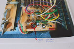
The one shown on the attached picture.
Did you end up finding a good replacement for this one?
Thank you for any help you could bring!!
Greetings from France!!
 

Attachments

  • s-l1600.jpg
    s-l1600.jpg
    249.2 KB · Views: 240
i think the only solution is going to be using depletion mode MOSFETs. they have the proper voltage ratings, but most of them are power transistors.... it's going to take some bit of searching to find a small enough device.
 
**broken link removed**

there are several devices there that should work, however they are all SMT devices, so you will need to work around that somehow.
 
Status
Not open for further replies.

Latest threads

New Articles From Microcontroller Tips

Back
Top