Continue to Site

Welcome to our site!

Electro Tech is an online community (with over 170,000 members) who enjoy talking about and building electronic circuits, projects and gadgets. To participate you need to register. Registration is free. Click here to register now.

  • Welcome to our site! Electro Tech is an online community (with over 170,000 members) who enjoy talking about and building electronic circuits, projects and gadgets. To participate you need to register. Registration is free. Click here to register now.

replaceing mic input with line in on fm transmitter

Status
Not open for further replies.

darklordchris

New Member
Oh... So many formulas...

There are quite a few formulas involved with this one. If at all possible, list exactly which components you would like values for.
 
The volume control is a simple voltage divider. When the log pot is set to half-way then it divides the input signal down to 1/10th its voltage.
 
There are quite a few formulas involved with this one. If at all possible, list exactly which components you would like values for.


The volume control is a simple voltage divider. When the log pot is set to half-way then it divides the input signal down to 1/10th its voltage.


ok well i was thinking about building these 2 projects, and maybe so other low power transmitters at some point, mostly from designs on this site i think,
and it would be nice if i knew how to sub the mics for in lines myself, rather then having to ask here every time i build something. so if you guys have any ideas please assist.

Free Kit Plans - Build your own FM Transmitter

Simple FM Transmitter
 
The extremely simple FM transmitter circuits you found have very poor performance:
1) The antenna is connected directly to the LC tuned circuit so the frequency will change if something moves toward the antenna or moves away.
2) There is no voltage regulator so the frequency will change as the battery voltage runs down.
3) There is no pre-emphasis (treble boost) like all FM radio stations have so sounds heard on a radio with de-emphasis (all radios have) will be muffled like your stereo with its treble tone control turned all the way down.
4) It is mono, not stereo.

I made the first circuit to see how bad it was (because somebody complained that it didn't work) then I fixed and improved it.
I added an output RF amplifier to isolate the antenna from the LC tuned circuit and give more range.
I added a low-dropout voltage regulator.
I added pre-emphasis so it sounds perfect.


ok, well how would i do that? what do i need to change in the diagram?i mean i mostly just need to know componet values and placement of the new parts

and can ypu recomend any other transmitter circuits to a kinda beginer such as myself?
 
Last edited:
You can make my fixed and improved FM transmitter if you want:
 

Attachments

  • FM transmitter pic + schem.PNG
    FM transmitter pic + schem.PNG
    195.9 KB · Views: 2,694
I used my FM transmitter for only one hour because I was freaked out thinking that I might be arrested by the RF cops.
 
My city and the cities around me have many FM radio stations so my dial is full.
I used the frequency of a low power foreign language station on the other side of my city so my transmitter caused interference to it.

My range was over 2km across a wide river valley to my very sensitive home stereo and car radio, 300m to my Sony Walkman radio and across the street to a "scanning" FM radio from The Dollar Store.


well yes that kind of interferance could alert legal bodys, good thing the radio cops aren't really a quick response kind of force.

i almost forgot, so what can i do to learn how to substune microphones for lines in on variuos trnsmitter disigns?
 
so what can i do to learn how to substune microphones for lines in on variuos trnsmitter disigns?
Do you want to substitute line-level signals for the microphone level signals?
Then simply remove the resistor that powers the microphone and add an attenuator made with 2 or 3 resistors. Use 3 resistors to mix left and right stereo channels and attenuate.
 
Do you want to substitute line-level signals for the microphone level signals?
Then simply remove the resistor that powers the microphone and add an attenuator made with 2 or 3 resistors. Use 3 resistors to mix left and right stereo channels and attenuate.


that would be the r1 resistor right?

also what kind of a componet is LM2931A 5.0? i'm not familiar with it
 
Yes, remove R1 and make a passive mixer/attenuator with 3 resistors.

The LM2931A 5.0 is a low-dropout 5V regulator that still regulates perfectly when the 9V battery voltage has dropped to 5.5V. An ordinary 7805 regulator fails to regulate when the battery drops to less than 8V. The battery voltage quickly drops to less than 7V. The transmitter's frequency changes if the 5V changes.


ok, i understand that, is it easy to find?
also could you tell me abit more about attenuators. like what vaules should it have, i don't really know anything about them.

most of my electronics lnowledge comes from rewiring electric guitars, and a basic 1 term intro to electronics class
 
all semiconductor IC manufacturers make 5V low-dropout voltage regulators. the LM2931 is made by National Semi and they make many different ones.

Try this for a mixer/attenuator:
 

Attachments

  • attenuator.PNG
    attenuator.PNG
    4.1 KB · Views: 257
wh
hi. been working on accouple of fm transmitters, and i have been wondering about replacing the mic input with a line in to a cd player or other audio source.

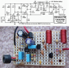
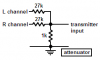
i built a kit the other day i had, https://www.electro-tech-online.com/custompdfs/2009/05/illustrated_assembly_manual_k1771_rev1.pdf

on page 9 of the manual they show you how to do it, but they don't really explain the formula behind it, so i was hoping someone on the board could give me a little knowlegde about ths:rolleyes:
where is the pdf
 
will it
all semiconductor IC manufacturers make 5V low-dropout voltage regulators. the LM2931 is made by National Semi and they make many different ones.

Try this for a mixer/attenuator:
work on every fm transmitter i mean same resisitance value for line -in
 
all semiconductor IC manufacturers make 5V low-dropout voltage regulators. the LM2931 is made by National Semi and they make many different ones.

Try this for a mixer/attenuator:
can i use your attenuater circuit with my fm transmitter that i mentioned and will this fm transmitter will work plz reply soon thanks.
 

Attachments

  • simple fm circuit.jpg
    simple fm circuit.jpg
    81.4 KB · Views: 97
Status
Not open for further replies.

Latest threads

New Articles From Microcontroller Tips

Back
Top