Continue to Site

Welcome to our site!

Electro Tech is an online community (with over 170,000 members) who enjoy talking about and building electronic circuits, projects and gadgets. To participate you need to register. Registration is free. Click here to register now.

  • Welcome to our site! Electro Tech is an online community (with over 170,000 members) who enjoy talking about and building electronic circuits, projects and gadgets. To participate you need to register. Registration is free. Click here to register now.

Repairing Clarion MCD 360 Crossover

Status
Not open for further replies.

kasey

New Member
Ok so I am reparing a clarion MCD360 Crossover. The problem is that it is not powering up at all i.e. the red power led is not illuminating when the remote terminal, the batt+ terminal and the ground terminal is connected to a reliable 12volt supply.

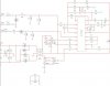
I obtained the service manual from online and traced the problem to the power supply stage, but I cannot seem to figure out what is the problem. Attached is the power supply stage schematic.

I am not getting any voltage out of T1 (The step up power supply transformer). On IC2, I am also not getting anything out of pins 9 and 10. I assumed the IC was bad and replaced it, but that did not solve the problem (my bad. lol) I also replaced ZD1 because I was getting voltage before it, but nothing after. But after replacing it, I got the same readings. So now I am perplexed as to what is the problem. No caps shorting, all resistors seem to be fine. What am I missing?
 

Attachments

  • ClarionCrossPwrSupply.JPG
    ClarionCrossPwrSupply.JPG
    77.8 KB · Views: 553
What voltages do you have on input P39-C and on pin 12 of the IC?
 
Can you list the voltages on all of the IC pins and on P39-A ?
 
Sorry for the late response. But here are the details you asked for:

Pin Voltage
1 0.050 Volts
2 2.048 Volts
3 0.051 Volts
4 0.042 Volts
5 1.699 Volts
6 3.529 Volts
7 0.000 Volts
8 12.17 Volts
9 3.318 Volts
10 3.856 Volts
11 12.20 Volts
12 11.35 Volts
13 5.03 Volts
14 5.03 Volts
15 4.36 Volts
16 2.048 Volts
 
Is the oscillator section of the TL594 working correctly? (Check pins 5 and 5 with an oscilloscope).
 
Is the oscillator section of the TL594 working correctly? (Check pins 5 and 5 with an oscilloscope).
I do not have an oscilloscope. And I think you meant pins 5 and 6??

Also, I replaced that IC with a new one bought from the store when I found no voltage going into T1. Could it be that the IC I bought and replaced, is defective also?
 
Last edited:
I think you meant pins 5 and 6?
Oops. Yes.
A pity you don't have a 'scope. A multi-meter with a frequency-measuring range would be handy instead.
It's always possible the replacement IC is faulty, but unlikely if bought from a reputable source.
 
In post #9 when you say "I found no voltage going into T1." Do you mean that there was no voltage on pin 2 of T1 ? If this is the case then check for a break in the track to that pin. This is because you have about 12 volts on pins 8 and 11 which are fed from the same supply via 10 ohm resistors.

Les.
 
Oops. Yes.
A pity you don't have a 'scope. A multi-meter with a frequency-measuring range would be handy instead.
It's always possible the replacement IC is faulty, but unlikely if bought from a reputable source.
Thanks for your input Alec. I think my meter can measure frequency. What exactly should I be looking for? What is a 'good reading' when measuring the frequency on pins 5 and 6?


In post #9 when you say "I found no voltage going into T1." Do you mean that there was no voltage on pin 2 of T1 ? If this is the case then check for a break in the track to that pin. This is because you have about 12 volts on pins 8 and 11 which are fed from the same supply via 10 ohm resistors.

Les.
Thanks for your input Les. When I said no voltage going into T1, I meant that I assumed that I would get an AC voltage going into pins 1 and 3 of the transformer (T1). I know T1 is a step up transformer and only AC can be stepped up. So no AC voltage BETWEEN pins 1 and 3.
 
What is a 'good reading' when measuring the frequency on pins 5 and 6?
With the component values listed, the oscillation frequency should be about 97kHz according to my LTspice simulation.
 
Status
Not open for further replies.

Latest threads

New Articles From Microcontroller Tips

Back
Top