Continue to Site

Welcome to our site!

Electro Tech is an online community (with over 170,000 members) who enjoy talking about and building electronic circuits, projects and gadgets. To participate you need to register. Registration is free. Click here to register now.

  • Welcome to our site! Electro Tech is an online community (with over 170,000 members) who enjoy talking about and building electronic circuits, projects and gadgets. To participate you need to register. Registration is free. Click here to register now.

Repair Sears Battery Charger

Status
Not open for further replies.

voglede

New Member
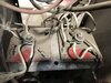
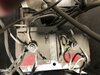
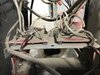
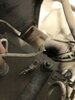
I have an old Sears Heavy Duty 40 Amp with a 225 Amp engine start. Model 934.718460. This unit has an old rectifier set up in it. From what I have been able to research, it is a bridge rectifier. There are 2 round discs on each side with 4 diodes on each. There are 4 wires running to each diode from a center post. The wires are a cloth sheathed wire, almost like they are fuseable wires. On the one side, all 4 wires look like they are connected, but the wire inside the sheathing is completely gone. They must have burned up at one time. I am going to assume that this means the rectifier is bad but does anyone know what the specs are on those wires? Can I replace them with regular gauge wire? Something like #12 or #14 to see if this will still work? If the rectifier is shot, is there any way to build a new one? The replacement rectifier for that charger is discontinued.

I understand that it is old technology and not very elegant, but the new chargers in that size are not the cheapest things around and I dislike how the new chargers are unable to charge a completely dead battery. I would like to resurrect this charger, if possible. I do not understand circuits well enough to build something from my own knowledge, but if someone were to tell me what I need and how to assemble it, I am good at following instructions.
 
Can you post some pictures of the overall rectifier assembly, and the details of the wiring?
 
Please excuse the dust. It will all get cleaned up if it is salvageable. The charger has been sitting for many years.
 

Attachments

  • B026138C-EC30-4615-BDB3-FDF1FCDD8EA0.jpeg
    B026138C-EC30-4615-BDB3-FDF1FCDD8EA0.jpeg
    2.6 MB · Views: 615
  • 3CA0B0B3-DD08-41A4-A70D-74D79003F78E.jpeg
    3CA0B0B3-DD08-41A4-A70D-74D79003F78E.jpeg
    2.6 MB · Views: 537
  • 7EBFE08F-B90E-4B45-A90B-F5CAAE07A55F.jpeg
    7EBFE08F-B90E-4B45-A90B-F5CAAE07A55F.jpeg
    2.5 MB · Views: 651
  • 1DC18F18-F7E2-4714-8893-1B4E5F4530EA.jpeg
    1DC18F18-F7E2-4714-8893-1B4E5F4530EA.jpeg
    1.1 MB · Views: 544
Ok, that's go to be one of the oddest mechanical layouts I've seen for rectifiers!

It looks like it uses two rectifier sections, each comprising four parallel diodes; the black riveted in items at the corners of each insulator.
If so the actual diagram will be similar to this:
main-qimg-fe605b24185fec753f8323a18b63097e


Except four diodes in parallel for each one there.

In that case there will be another connection to the transformer secondary somewhere else, one or two more of the heavy copper enamelled wires like on the big bolted terminals?


These look to be possibly the most economical and easy to mount devices for replacement use:

Data:

Each module gives you two, 90A rated diodes; one module should be fine for the normal 40A charge use.
If you wanted to allow the 225A rating, I'd use three of those in tandem.

Use appropriately rated wire, eg. two parallel runs of 6mm^2 for the output and one each for the AC input.

If using recs in parallel, make the connecting cables exactly the same length - they will be acting as load balancing resistors, at those currents.

The diode modules will need the base bolting on to a decent size aluminium heatsink.
 

or


And add a heat sink like this...

 
I'm always wary of things that do not have data sheets available; but at the price it could be worth trying.

The charger only appears to need a two-diode rec so only the AC in and (probably) + out would be used on a full bridge.
 
Last edited:
Status
Not open for further replies.

Latest threads

New Articles From Microcontroller Tips

Back
Top